CK721-A Installation and Operation Grounding and Connectors
24-10349-8 Rev. B C-3
This document contains confidential and proprietary information of Johnson Controls, Inc.
© 2012 Johnson Controls, Inc.
Non “D-Type” Grounding Connections
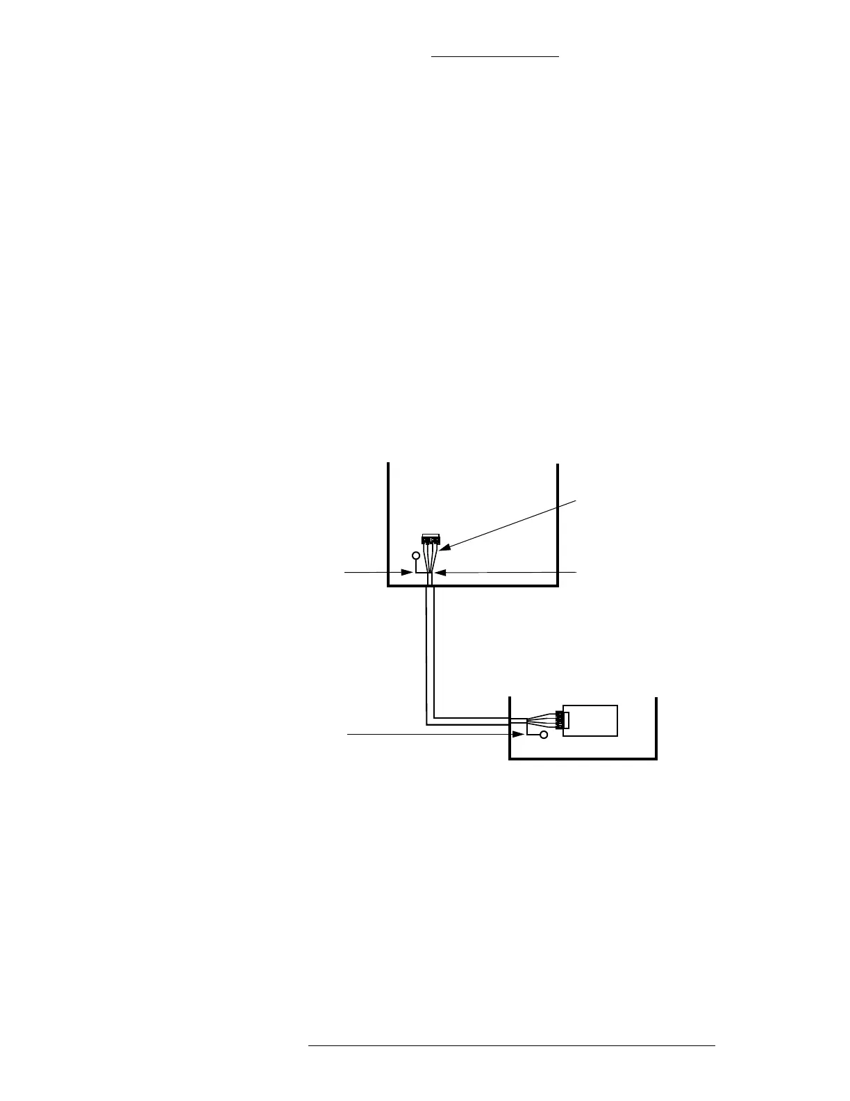
As shown in Figure C-2, incoming wires that are foil shielded with a drain wire are
connected to the grounding bus.
When using incoming wires that are foil shielded without
a drain wire, strip back the
insulation, twist the foil shield together, and using a customer-supplied crimp
terminal, splice a wire to the end of the shield. Terminate the wire with an insulated
spring spade terminal, and attach it to the enclosure ground stud.
Figure C-2: Example of Grounding Shielded Cable at Both Ends
Installations in the USA
In the USA, the two units are connected using shielded cable. As shown in Figure
C-2, ground the shield at both ends.
In some USA installations, operation of the sys
tem can be compromised by excess
ground currents travelling along the shield. Figure C-3 shows an alternate method of
shielding. Cables connected to user peripherals (printers, VDTs, etc.) should have
shields co
nnected at both ends.
Separated wires of
cable are not shielded
The screen-type shield is
inside the enclosure, no
more than 2" (5cm)
Short wire is
connected
from shield to
enclosure of
unit 1
Short wire is
connected
from shield to
enclosure of
unit 2
UNIT2
UNIT1
PCBA