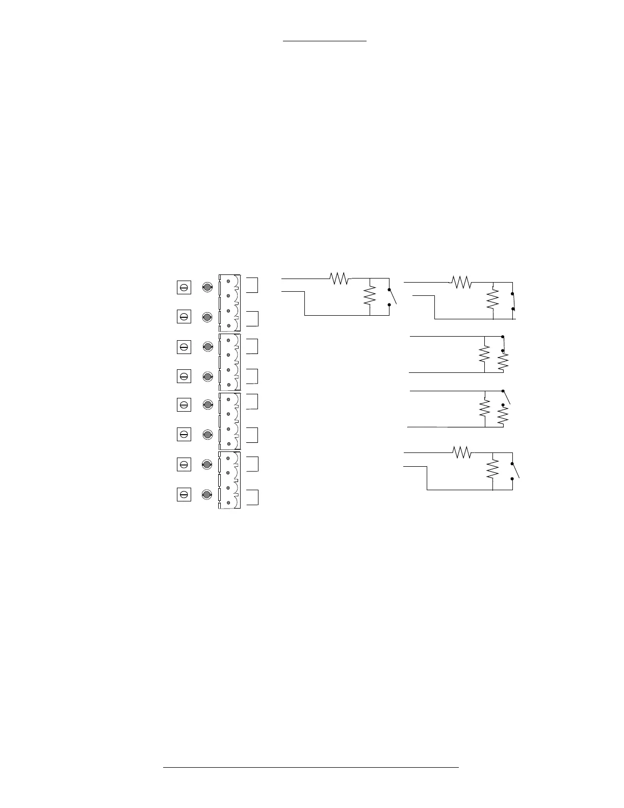
Figure 3-33: Four-state Alarm Inputs
Four-state alarms require 150 Ohms ±2%,
1/4 W resistors wired at the external
device to be in the secure condition.
Resistances above and below the secure 150 Ohm range
cause an alarm condition.
The 300 and 75 Ohms conditions cause high and low alarms respectively, as shown
in Figure 3-34.
The normal condition of the switch state (open or
closed) must be considered when
choosing the resistor configuration. For example, a normally open switch must have
150 Ohms when the switch is open and 75 Ohms when the switch is closed. A
normally closed switch must have 150 Ohms when closed and 300 Ohms when
open. Resistance values below 40 Ohms cause a short condition and resistance
above 500 Ohms causes an open condition.
S300 Expansion Enclosures CK721-A Installation and Operation
3-50 24-10349-8 Rev. B
This document contains confidential and proprietary information of Johnson Controls, Inc.
© 2012 Johnson Controls, Inc.
Supervised Alarm Inputs
The difference between the I16 or IO8 modules and the SIO8 or SI8 modules is that
the latter’s inputs are supervised. A supervised alarm input provides two additional
states. These additional states are used primarily for indicating a tamper to an
external alarm device. For more information regarding supervised and unsupervised
alarm inputs, see “Installing the First Level Modules” on pag
e 3-7.
The SIO8 and SI8 have four-state inputs. The state of each alarm is indicated by
a
multi-color LED adjacent to each pair of alarm inputs.
Green - Secure Red - Alarm
Yellow - Short
150
150
300
300
150
150
75
75
AL8
AL7
AL6
AL5
AL4
AL3
AL2
AL1
J6D
J6C
J6B
J6A
NC
NC
NO
NO
R3
R5
R4
R6
R7
R8
R9
R10
NC = Normally Closed
NO = Normally Open