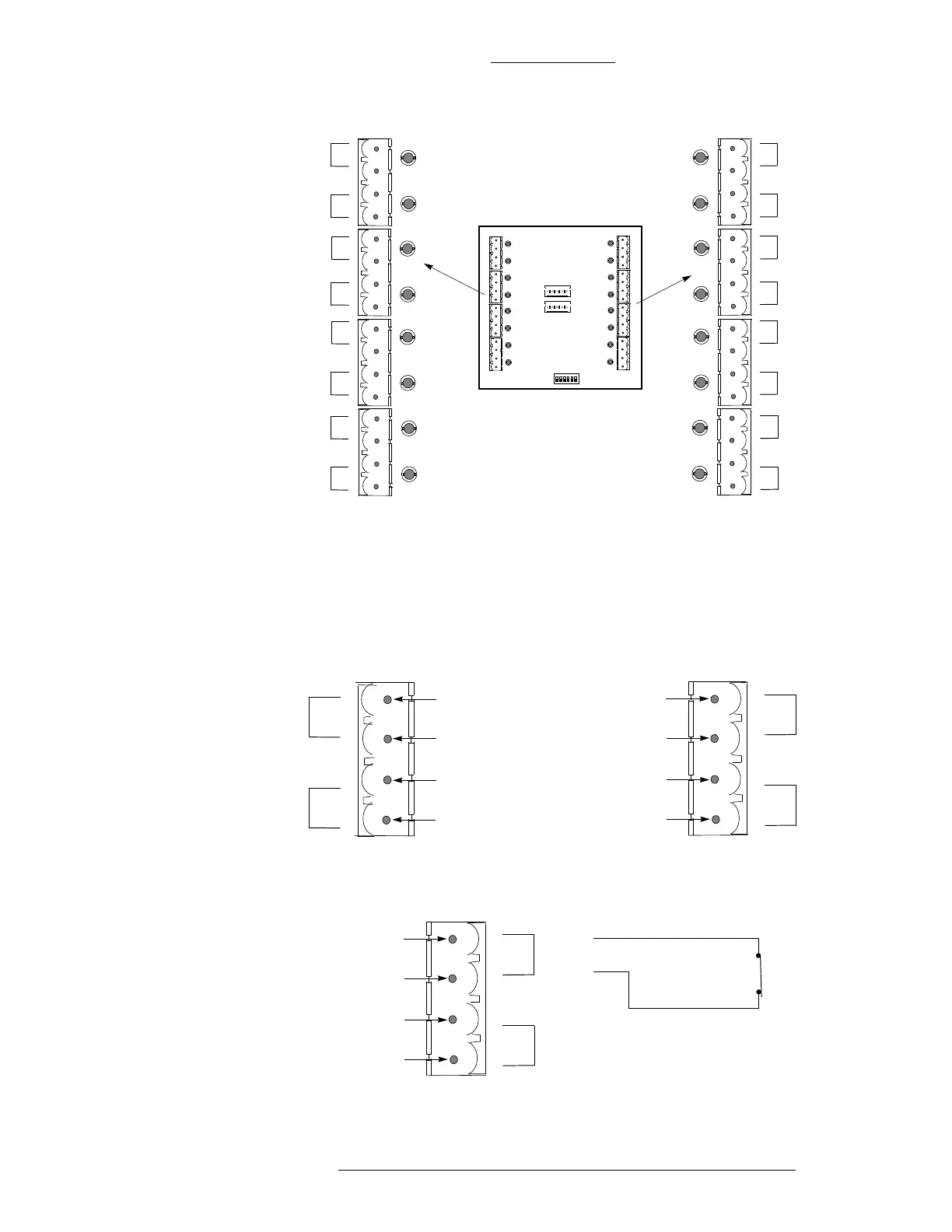
Figure 3-32: Circuit for two-state Inputs (normally closed)
Figure 3-31: Wiring Input Points (two and fou
r-state alarms)
AL2
AL1
Ground
Active
Ground
Active
AL8
AL7
AL6
AL5
AL4
AL3
AL2
AL1
AL16
AL15
AL14
AL13
AL12
AL11
AL10
AL9
Note
This diagram shows an S300-I16. For every input/output terminal,
the wiring of the input points are the same.
For every alarm pair,
the top pin is ground, the
second pin is active.
AL2
AL1
Ground
Active
Ground
Active
AL10
AL9
Ground
Active
Ground
Active
J1A J1B
J1C
J1D
J4D
J4C
J4BJ4A
CK721-A Installation and Operation S300 Expansion Enclosures
24-10349-8 Rev. B 3-49
This document contains confidential and proprietary information of Johnson Controls, Inc.
© 2012 Johnson Controls, Inc.