CK721-A Installation and Operation S300 Expansion Enclosures
24-10349-8 Rev. B 3-29
This document contains confidential and proprietary information of Johnson Controls, Inc.
© 2012 Johnson Controls, Inc.
Warm-up Resistor Removal
S300-RDR2 modules contain a filament warming circuit for use with standard
readers. The standard readers use incandescent lamps for void/valid indicators.
When readers with LEDs rather than incandescent indicators are connected to the
reader terminal, the warming circuit causes the reader’s LEDs to be constantly
illuminated.
When readers with LEDs as void/valid indicators
are used with S300-RDR2, the
warming resistors must be removed from the printed circuit board. See Table 3-15
for the corresponding resistor to reader that must be remov
ed.
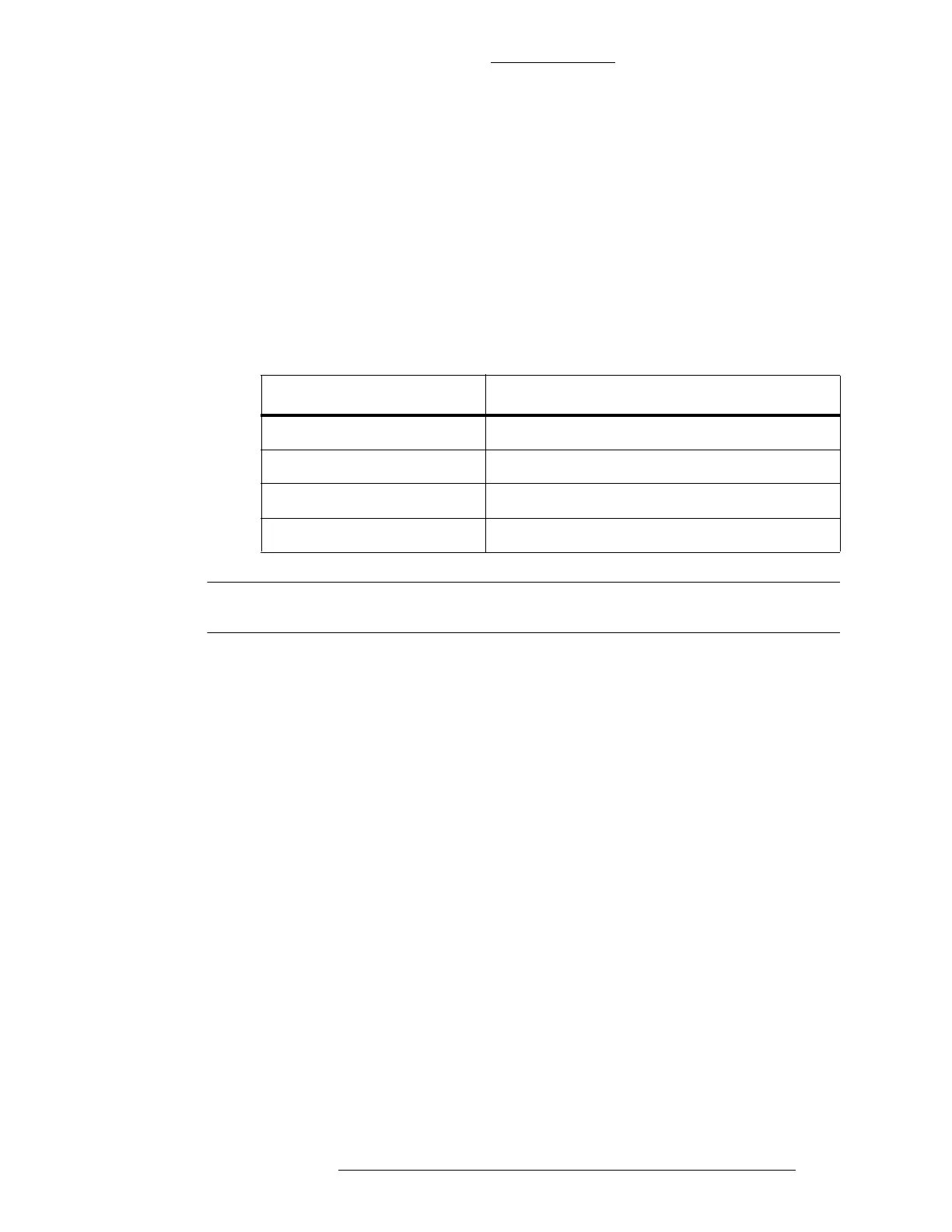
Table 3-15: S300-RDR2 Location
s of Warm-up Resistors
Remove Description
R6 reader 1, Red Lamp
R7 reader 2, Red Lamp
R8 reader 1, Green Lamp
R9 reader 2, Green Lamp
NOTE
Remove only the warming resistors that must be removed.