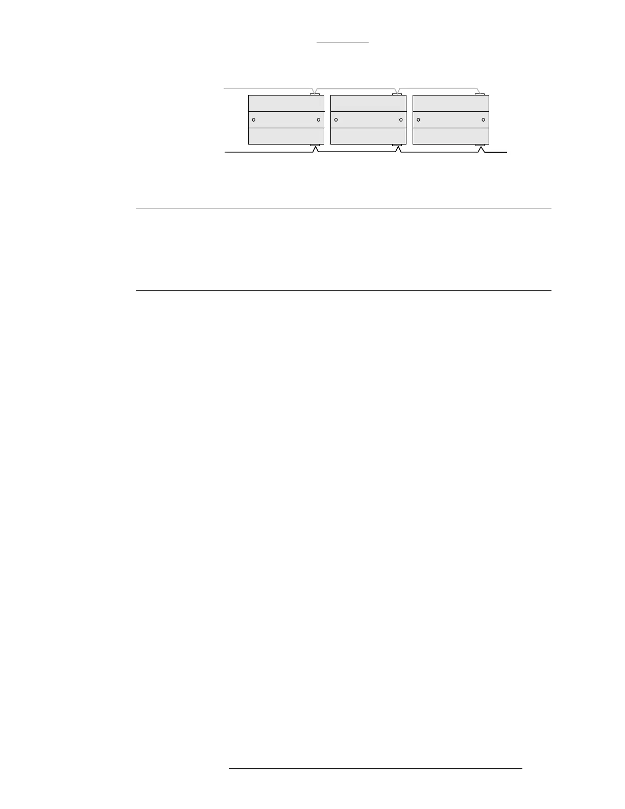
Figure 2-13: Wiring Multiple Modules - Overview
1st Module 3rd Module2nd Module
to the next
module
DC power cable
connecting to
power supply
RS-485 cable
CK721-A Installation and Operation CK721-A and S300-DIN Enclosures
24-10349-8 Rev. B 2-17
This document contains confidential and proprietary information of Johnson Controls, Inc.
© 2012 Johnson Controls, Inc.
IMPORTANT
Observe the following precautions:
Make sure each wire is connected to the same corresponding connector position
in the subsequent module.
Do not connect the DC power cable to the module until all wiring is complete.
Ground Wiring
For ground wiring with the either large or small enclosure, use the cable assembly
shown in Figure 2-12. The ground wire should be connected to the backplate by
fastening the ring terminal to any one of the 0.11" holes located at the bottom of the
plate with
a #6 self-tapping screw.
When connecting CK721-A to multiple S300-DIN modules, wire them in parallel
following the “daisy
chain” pattern as shown in Figure 2-13. For wiring details refer
to the documentation provided with the S300-DIN module.
To construct the ground wiring, use 18AWG wires.