S300 Expansion Enclosures CK721-A Installation and Operation
3-42 24-10349-8 Rev. B
This document contains confidential and proprietary information of Johnson Controls, Inc.
© 2012 Johnson Controls, Inc.
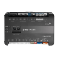
Table 3-19: S300-I16 Components
Component Description
J1A Alarm Inputs 9 and 10
J1B Alarm Inputs 11 and 12
J1C Alarm Inputs 13 and 14
J1D Alarm Inputs 15 and 16
J2 RS-485 Input
J3 RS-485 Output
J4A Alarm Inputs 1 and 2
J4B Alarm Inputs 3 and 4
J4C Alarm Inputs 5 and 6
J4D Alarm Inputs 7 and 8
SW1
Address Settings (refer to Chapter 4: CK721-A User
Interface)
System LEDs Indicate when data is transmitted or received and the presence
of 5 and 12 VDC, as labeled in the diagram above
U3 S300-I16 Firmware
 Loading...


