4 Electrical connection
26
4.3 Connection diagram
4.3.1 Connection elements
DANGER!
Works involving dangerous electrical voltage (230 V) are performed here.
There is a risk of electric shock.
De-energize all electrical circuits before performing wiring work. The electrical connec-
tion must only be established by qualified personnel.
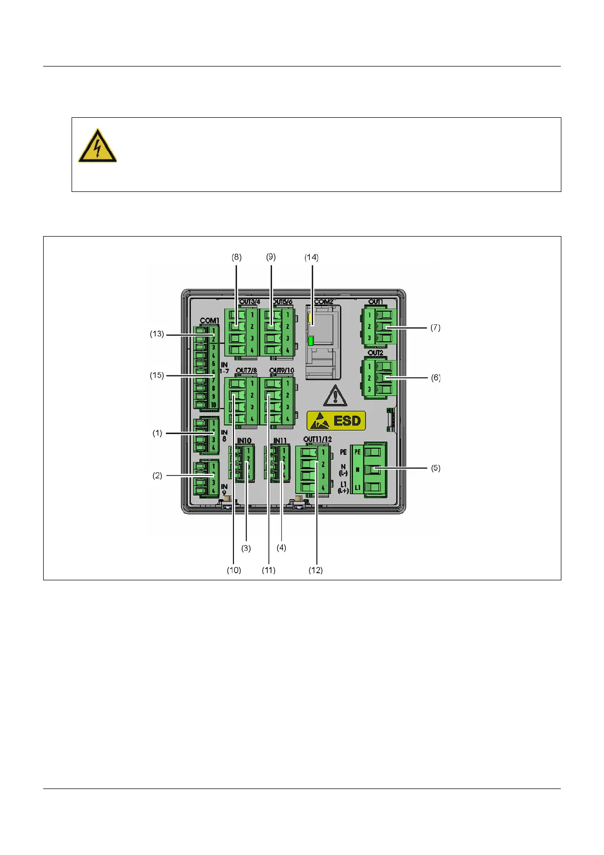
(1) Analog input IN8 (2) Analog input IN9
(3) Expansion slot for analog input IN10 (4) Expansion slot for analog input IN11
(5) Voltage supply
AC 240 V +10/-15 %, 48 to 63 Hz,
AC/DC 24 V +30/-25 %, 48 to 63 Hz
(6) Relay output OUT2
(7) Relay output OUT1 (8) Expansion slot for outputs OUT3/4
(9) Expansion slot for outputs OUT5/6 (10) Expansion slot for outputs OUT7/8
(11) Expansion slot for outputs OUT9/10 (12) Expansion slot for outputs OUT11/12
(13) COM1 interface RS485 (14) Expansion slot for COM2 interface
(15) Digital inputs IN1 to 7