39
5 Operation
5.5 Screens in the operating loop
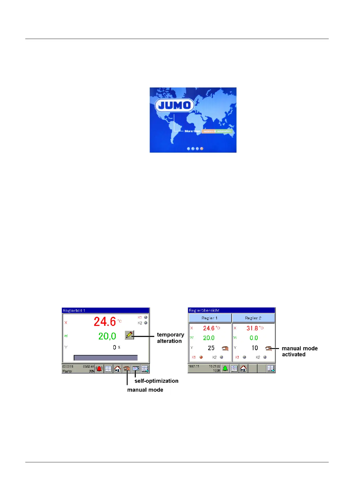
Start screen
After switch-on, the globe appears until the device software is started up.
Then controller screen 1 appears (default setting).
Using the icon in the bottom right-hand corner, all the screens defined in the operating loop can
be called up one after another.
Ö For the screen settings, see the operating manual Chapter 12.10 "Screen", Page 112
Ö For information on which screens are displayed, see operating manual Chapter 12.10.4
"Operation loop", Page 114
5.5.1 Controller screen 1 to 4 and controller overview screens 1, 2
These screens can be edited in the setup program.
Ö Chapter 12.10.6 "Colors, designations in controller screen 1 to 4", Page 116
Default setting
Fixed-setpoint controller and Controller 1 are set up.
In order to function properly, the controller requires an actual value, a setpoint value, and an
output that influences the actual value (for example, a heat source via a relay as a two-state
controller). Autotuning can only detect new parameters with a closed control loop.
Ö Chapter 12.6.3 "Controller self-optimization", Page 84
If lines or arrows appear, check the configuration or the connection.
Ö Chapter 16 "Error and alarm messages", Page 181
Entering setpoint values on the device for the fixed-setpoint controller
Ö Chapter 11.4 "Setpoint values", Page 64
Entering setpoint values for the fixed-setpoint controller using the setup program
Ö Chapter 11.4 "Setpoint values", Page 64