12 Configuration
78
Lead wire resistance
When connecting an RTD probe in a two-wire circuit, longer lines may lead to measuring errors.
This value is used to compensate the resistance of the probe line and depends on the line
length. Enter the ohmic resistance of the probe line here to achieve the best possible temper-
ature measurement.
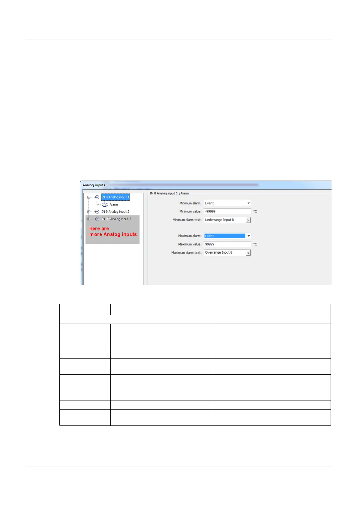
12.5.1 Alarms
A limit value monitoring function with one or two alarms and various alarm types can be acti-
vated for each analog input. In addition, this function is required in order to trigger the collective
alarm of the controller module in the event of deviation above or below the measuring range
(out of range).
This limit value monitoring function is available in addition to the functions described in Chapter
12.9 "Limit value monitoring function", page 106 and is independent of these functions.
Setup dialog box
Parameters
Parameter Selection/settings Description
IN 8 Analog input 1, IN9 Analog input 2
Minimum alarm Off Monitoring is not active.
Alarm Alarm results in an entry in the alarm list.
Event Alarm results in an entry in the event list.
Minimum value -99999 to 0 to +99999 Limit value at which an alarm is issued.
Minimum alarm
text
Underrange AI1 Text which is entered into the alarm or
event list if the value is exceeded.
Maximum alarm Off Monitoring is not active.
Alarm Alarm results in an entry in the alarm list.
Event Alarm results in an entry in the event list.
Maximum value -99999 to 0 to +99999 Limit value at which an alarm is issued.
Maximum alarm
text
Overrange AI1 Text which is entered into the alarm or
event list if the value is exceeded.