31
4 Electrical connection
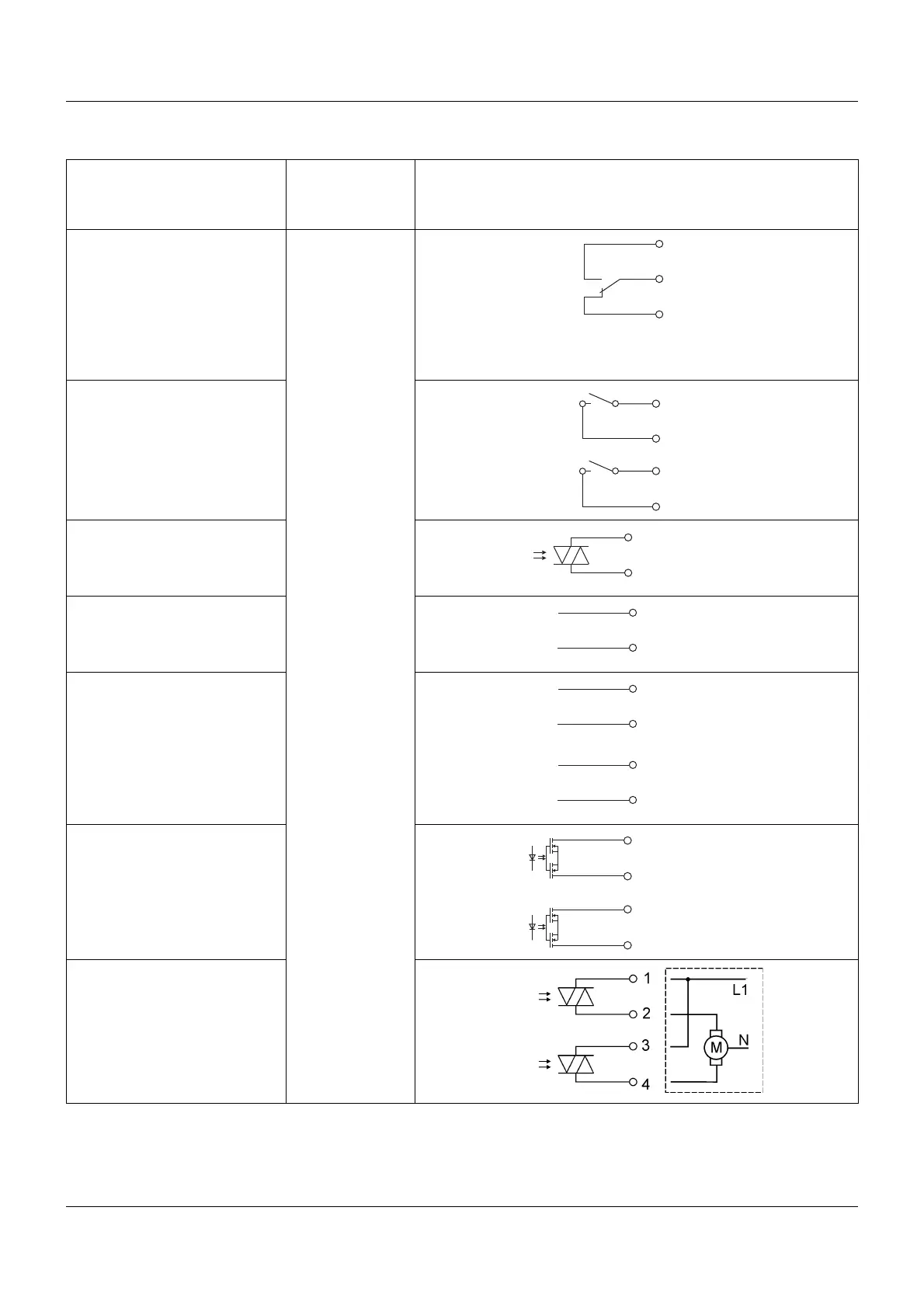
Outputs OUT 3/4 to 11/12 can be expanded via the following optional boards
Connection (Connection
element)
Output
Symbol and terminal designation
1 relay output (changeover
contact)
(8) OUT3/4
(9) OUT5/6
(10) OUT7/8
(11) OUT9/10
(12) OUT11/12
1
2
3
2 relay outputs (N/O contact)
1
1
2
3
4
1 solid state relay
AC230V, 1A
1
2
1 logic output
DC 0/22 V, max. 30 mA
(short-circuit proof)
1
2
2 logic outputs
DC 0/12 V max. 20 mA
(short-circuit proof,
not galvanically isolated from
each other)
1
2
3
4
2 PhotoMOS® relays
2
max. DC 45 V, 200 mA
max. AC 30 V, 200 mA
(galvanically isolated)
1
2
3
4
2 solid state relays
AC230V, 1A
(for controlling the left and
right-hand motor actuators,
galvanically isolated)
1
Combining mains voltage and protective low-voltage circuits on a 2-way N/O contact option is not admissible.
2
PhotoMOS is a registered trademark of the Panasonic Corporation.