83
12 Configuration
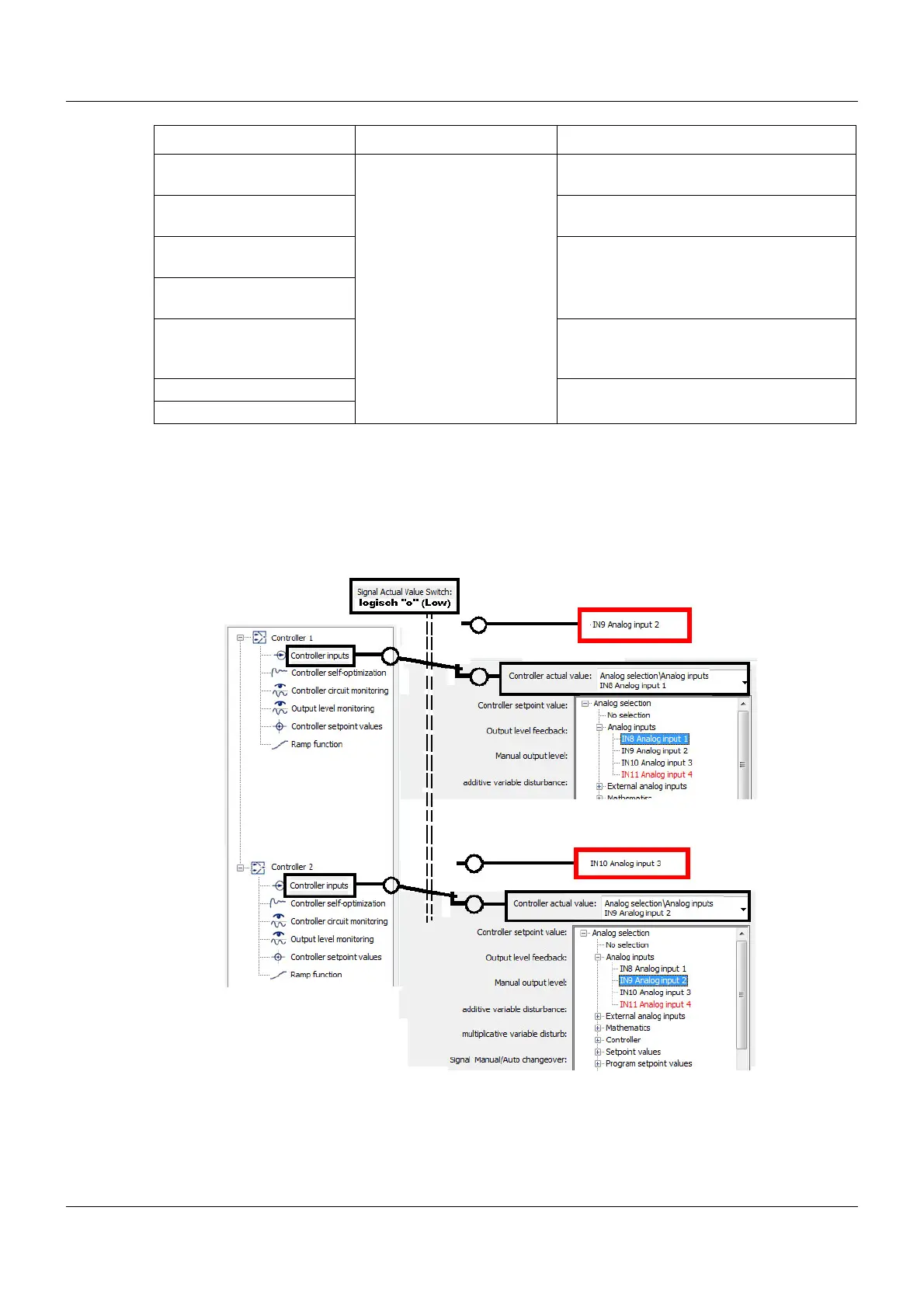
Actual value switching
Provided that no signal has been selected for switching the actual value, the actual values from
the analog selector that were set during the controller configuration are active. If, however, a
signal is set for switching the actual value, then with the High signal level (logic level 1) the sys-
tem switches to the actual values outlined in red.
Controller 1 is then linked to IN9 (analog input 2) and Controller 2 to IN10 (analog input 3).
Signal Manual/Auto
changeover
No selection
Digital selector
This signal switches between manual
mode and automatic mode.
Signal Manual mode lock-
ing
This signal locks manual mode
Signal 1
parameter block switching
The parameter blocks entered in Chapter
11.3 "Controller/parameter blocks", page
60 are switched using both these signals.
Signal 2
parameter block switching
Signal for actual value
switching
The analog inputs (actual value inputs)
are switched using this digital signal.
Controller off signal The controller can be switched to On or
Off using this signal.
Controller on signal
Parameter Selection/settings Description