Lenze · 8400 HighLine · Reference manual · DMS 12.0 EN · 06/2017 · TD23 471
7 Technology applications
7.5 TA "Switch-off positioning"
_ _ _ _ _ _ _ _ _ _ _ _ _ _ _ _ _ _ _ _ _ _ _ _ _ _ _ _ _ _ _ _ _ _ _ _ _ _ _ _ _ _ _ _ _ _ _ _ _ _ _ _ _ _ _ _ _ _ _ _ _ _ _ _
Outputs
GP: GeneralPurpose
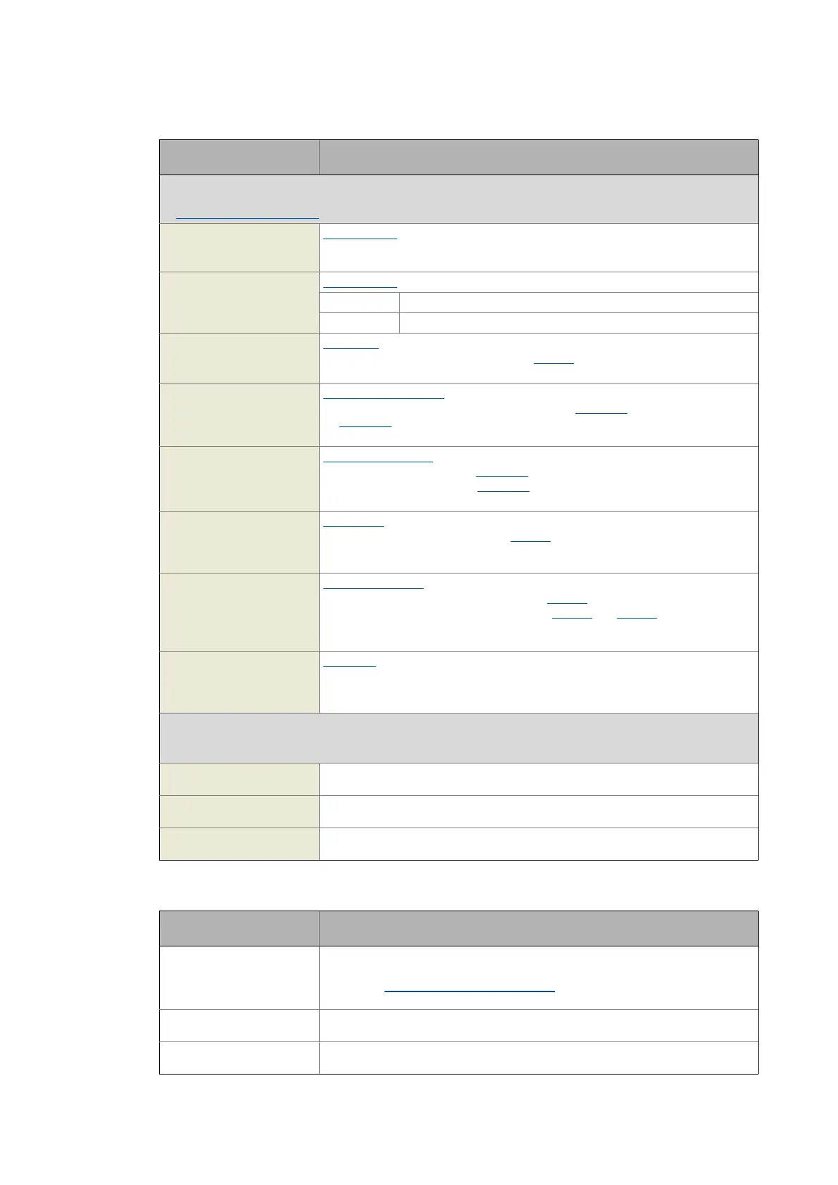
The following inputs are interconnected with logic/arithmetic functions on application level for free usage.
"GeneralPurpose" functions
nGPAnalogSwitchIn1_a
nGPAnalogSwitchIn2_a
INT
Analog switch: Input signals
• The input signal selected via the selection input bGPAnalogSwitchSet is output at
output nGPAnalogSwitchOut_a.
bGPAnalogSwitchSet
BOOL
Analog switch: Selection input
FALSE nGPAnalogSwitchOut_a = nGPAnalogSwitchIn1_a
TRUE nGPAnalogSwitchOut_a = nGPAnalogSwitchIn2_a
nGPArithmetikIn1_a
nGPArithmetikIn2_a
INT
Arithmetic: Input signals
• The arithmetic function is selected in C00338
.
• The result is output at output nGPArithmetikOut_a.
nGPMulDivIn_a
INT
Multiplication/Division: Input signal
• The factor for the multiplication can be set in C00699/1
(numerator) and
C00699/2
(denominator).
• The result is output at output nGPMulDivOut_a.
bGPDigitalDelayIn
BOOL
Binary delay element: Input signal
• The on-delay can be set in C00720/1
.
• The off-delay can be set in C00720/2
.
• The time-delayed input signal is output at output bGPDigitalDelayOut.
bGPLogicIn1
bGPLogicIn2
bGPLogicIn3
BOOL
Binary logic: Input signals
• The logic operation is selected in C00820
.
• The result is output at output bGPLogicOut.
nGPCompareIn1_a
nGPCompareIn2_a
INT
Analog comparison: Input signals
• The comparison operation is selected in C00680
.
• Hysteresis and window size can be set in C00680
and C00682.
• If the comparison statement is true, the output bGPCompareOut will be set to
TRUE.
bGPDFlipFlop_InD
bGPDFlipFlop_InClk
bGPDFlipFlop_InClr
BOOL
D-FlipFlop: Input signals
• Data, clock and reset input
Free inputs
The following inputs can freely be interconnected on the application level.
The signals can be transferred from the I/O level to the application level via these inputs.
bFreeIn1 ... bFreeIn8
BOOL
Free inputs for digital signals
wFreeIn1 ... wFreeIn4
WORD
Free inputs for 16-bit signals
dnFreeIn1_p ... dnFreeIn2_p
DINT
Free inputs for 32-bit signals
Designator
Data type
Value/meaning
wDriveControlStatus
WORD
Status word of the inverter
• The status word contains information on the currents status of the inverter.
• See the "wDeviceStatusWord status word
" subchapter of the chapter on device
control for a detailed description of the bit assignment.
wStateDetermFailNoLow
WORD
Display of the status determining error (LOW word)
wStateDetermFailNoHigh
WORD
Display of the status determining error (HIGH word)
Designator
Data type
Information/possible settings
 Loading...


