Lenze · 8400 HighLine · Reference manual · DMS 12.0 EN · 06/2017 · TD23 485
7 Technology applications
7.5 TA "Switch-off positioning"
_ _ _ _ _ _ _ _ _ _ _ _ _ _ _ _ _ _ _ _ _ _ _ _ _ _ _ _ _ _ _ _ _ _ _ _ _ _ _ _ _ _ _ _ _ _ _ _ _ _ _ _ _ _ _ _ _ _ _ _ _ _ _ _
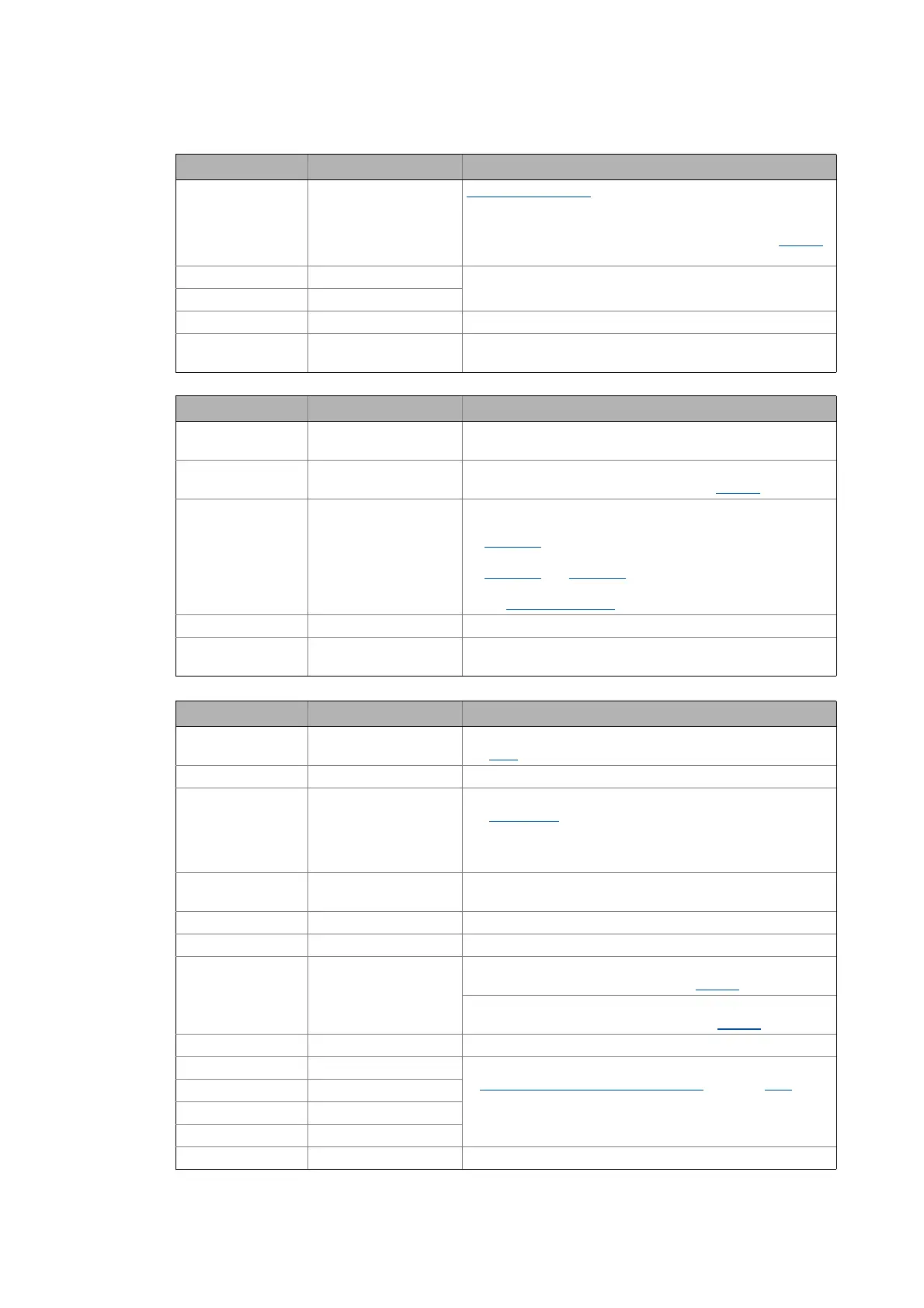
Bit 11 MBrkRelease Holding brake control:
0 ≡ Apply brake
1 ≡ Release brake
• In conjunction with the operating mode selected in C02580
(Lenze setting: "Brake control off").
Bit 12 JogCtrlJog1 Binary coded selection of the fixed setpoints (JOG setpoints)
Bit 13 JogCtrlJog2
Bit 14 SetFail 1 ≡ Set error (trip set)
Bit 15 SetSpeedCcw 0 ≡ Direction of rotation to the right (Cw)
1 ≡ Direction of rotation to the left (Ccw)
Output words Name Assignment
Word 1 DriveControlStatus Status word
• For bit assignment see the table below.
Word 2 MotorSpeedAct Actual speed value
• Scaling: 16384 ≡ 100 % reference speed (C00011
)
Word 3 GPSignalOut1 Analog signal monitor: Output signal 1
• The selection of the signal source to output is executed in
C00410/1
.
• Gain and offset for the output signal can be parameterised in
C00413/1
and C00413/2.
• For a detailed functional description see
the L_SignalMonitor_a
FB.
Word 4 - Not preconfigured
Words 5 ... 16 - Not preconfigured
• Only available in control mode "40: MCI".
Status word Name Status
Bit 0 DriveFail 1 ≡ Inverter in the error status
•"Fault
" device status is active.
Bit 1 PowerDisabled 1 ≡ Inverter control inhibited (pulse inhibit is active)
Bit 2 DriveReady 1 ≡ Inverter is ready for operation
•"SwitchedOn
" device status is active.
• The drive is in this device status if the DC bus voltage is
applied and the inverter is still inhibited by the user
(controller inhibit).
Bit 3 SpeedCcw 0 ≡ Direction of rotation to the right (Cw)
1 ≡ Direction of rotation to the left (Ccw)
Bit 4 QSPIsActive 1 ≡ Quick stop is active
Bit 5 BrakeReleased 1 ≡ Brake released (after the brake opening time has elapsed)
Bit 6 ActSpeedIsZero During open-loop operation:
1 ≡ Speed setpoint < Comparison value (C00024
)
During closed-loop operation:
1 ≡ Actual speed value < Comparison value (C00024
)
Bit 7 ControllerInhibit 1 ≡ Inverter is inhibited (controller inhibit is active)
Bit 8 StatusCodeBit0 Bit coded display of the active device status
Device state machine and device states
(see table [4-1])
Bit 9 StatusCodeBit1
Bit 10 StatusCodeBit2
Bit 11 StatusCodeBit3
Bit 12 Warning 1 ≡ a warning is indicated
Control word Name Function