Actions Yes No
Step 5
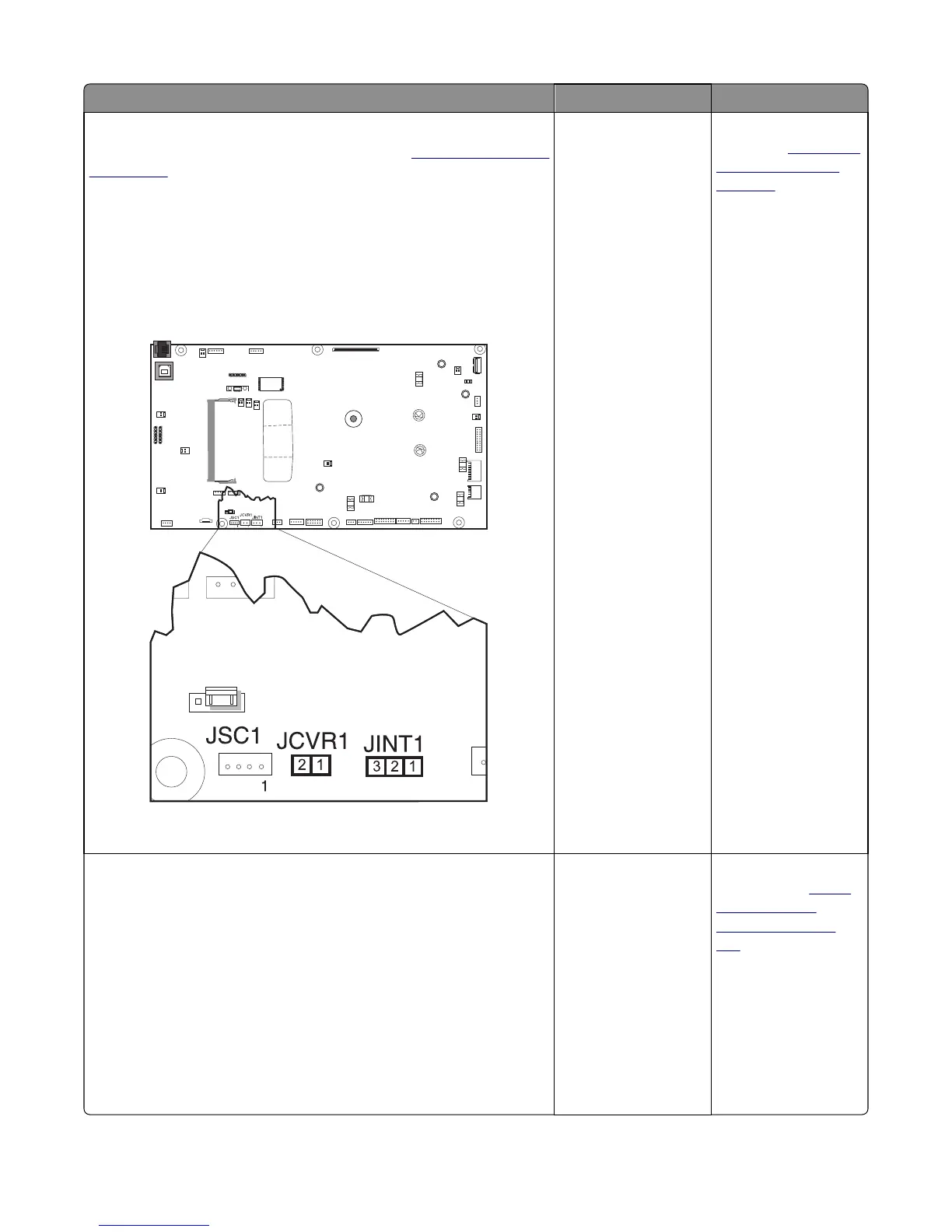
Turn the printer off, and remove the rear cover. See
“Rear cover removal”
on page 290. Turn the printer on, and verify the following values at JINT1
and JCVR1.
JINT1
Pin 1: +5 V dc
Pin 2: Ground
JCVR1
Pin 1: +24 V dc
Are the values approximately correct?
Go to step 6. Replace the controller
board. See
“Controller
board removal” on
page 291.
Step 6
Close the front cover and the toner door. Be sure that the right cover is
in place. Turn the printer off, and then disconnect the cables at JINT1 and
JCVR1.
Test continually at the connector under the following conditions:
• With the front cover and toner door closed: Test pin 1 and pin 3 at
JINT1 cable end, and pin 1 and pin 2 at JCVR1 cable end.
• With one or both doors open: Pin 2 and 3 at JINT1 cable end should
indicate continuity, but pins 1 and 2 at JCVR1 should have no
continuity.
Are the tests verified?
Contact your next level
or support.
Replace the front cover
assembly. See
“Front
cover assembly
removal” on page
252.
5027
Diagnostic information
122