5
Service work
Self-help
2
3
45
6
7
89
10 11
1
e3871140
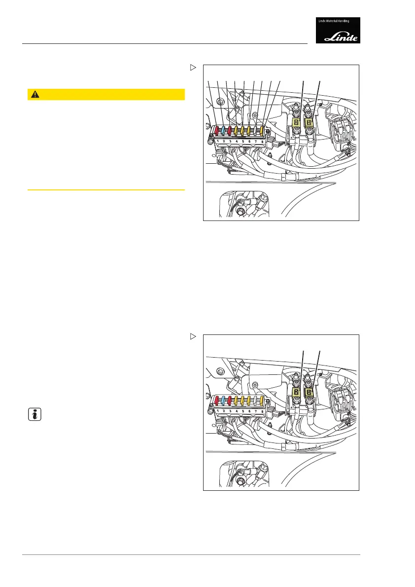
1 Fuse4F1,10A,horn
2 Control current fuse F2, 15 A
3 Fuse for discharge indicator F3, 10 A
4 Fuse F4, 5 A, voltage transformer (13 V)
5 Fuse 9F5, 5 A, fan (9M1-9M7)
6 Fuse 2F6, 5 A, discharge circuit
7 Fuse F7, 10 A, discharge circuit
8 Fuse 1F8, 5 A, discharge circuit
9 Clear cover for base plate
10 Fuse 2F1, 355 A, pump motor
11 Fuse 1F1, 355 A, traction motors
Checking the fuses -
Replacing as required
CAUTION
Risk of fire if automotive f
uses are used.
Only use genuine Linde sp
arefuseswithahigh
voltage rating.
Automotive fuses must
not be used under any
circumstances.
The control current f
uses are equipped with a
special quartz sand
filling and are designed for a
higher voltage ran
ge.
Contact your servi
ce partner.
Remove the cover (9
) from the fuse holder.
Replace the defective fuses.
10 11
e3871140a
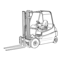
10 2F1 fuse for pump motor, 355 A
11 1F1 fuse for traction motors, 355 A
Checking the main current fuses -
Replacing as required
The two
main current fuses for the traction
motors
and the pump motor are located on the
main
contactor.
Replace the defective fuses.
NOTE
The fuse elements must be correctly fitted.
The assembly sequence for the individual
components must be observed. Contact your
service partner.
268 Operating Instructions – 3888011701 EN – 12/2017