262334 237 Revision A
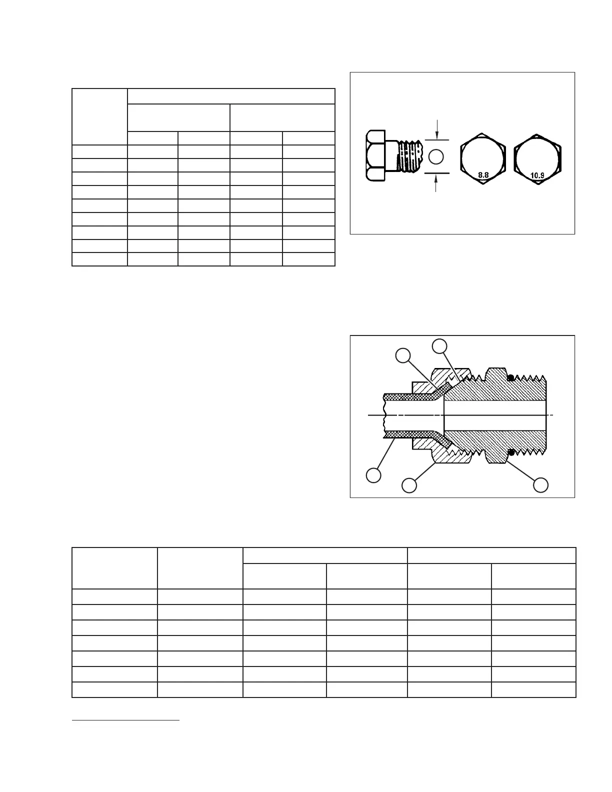
Figure 7.9: Bolt Grades
Table 7.9 Metric Bolt Bolting into Cast Aluminum
Nominal
Size (A)
Bolt Torque
8.8
(Cast Aluminum)
10.9
(Cast Aluminum)
Nm
lbf·ft
Nm
lbf·ft
M3
–– –
1
M4
––
4
2.6
M5
––
8
5.5
M6 9 6 12 9
M8 20
14
28 20
M10 40 28
55
40
M12 70 52 100 73
M14
–– – –
M16
–– – –
Flare-Type Hydraulic Fittings
The standard torque values are provided for flare-type hydraulic fittings. If a procedure specifies a different torque value
for the same type and size of fitting found in this topic, refer to the value specified in the procedure instead.
Figure 7.10: Hydraulic Fitting
1. Inspect flare (A) and flare seat (B) for defects that might
cause leakage.
2. Align tube (C) with fitting (D) and thread nut (E) onto the
fitting without lubrication until contact is made between
the flared surfaces.
3. Torque fitting nut (E) to the specified number of flats from
finger tight (FFFT) or to a given torque value in Table 7.10,
page 237.
4. Secure fitting (D) with two wrenches. Place one wrench on
fitting body (D), and tighten nut (E) with the other wrench
to the torque value shown in Table 7.10, page 237.
5. Verify the final condition of connection.
Table 7.10 Flare-Type Hydraulic Tube Fittings
SAE Dash Size
Thread Size (in.)
Torque Value
5
Flats from Finger Tight (FFFT)
Nm
lbf·ft Tube
Swivel Nut or
Hose
-2
5/16–24
4–5
3–4
——
-3
3/8–24
7–85–6
——
-4
7/16–20
18–19 13–14
2 1/2
2
-5
1/2–20
19–21
14–15
22
-6
9/16–18
30–33
22–24 2
1 1/2
-8
3/4–16
57–63 42–46
2
1 1/2
-10
7/8–14
81–89 60–66
1 1/2 1 1/2
REFERENCE
5. Torque values shown are based on lubricated connections as in reassembly.