262334 47 Revision A
Figure 3.39: Modified Routing M100, M105, and M205
18. For procedure to change hose routing for M100 or M105
Self-Propelled Windrowers, refer to 3.5.6 Routing A40D
Auger Header Hydraulic Drive Hoses, page 65.
3.5.2 Attaching A40D Auger Header to an M150, M155, or M155E4 Self-Propelled
Windrower
The header’s hydraulic multicoupler must be connected to the windrower before operation.
DANGER
To prevent injury or death from the unexpected start-up of the machine, always stop the engine and remove the key
from the ignition before leaving the operator’s seat for any reason.
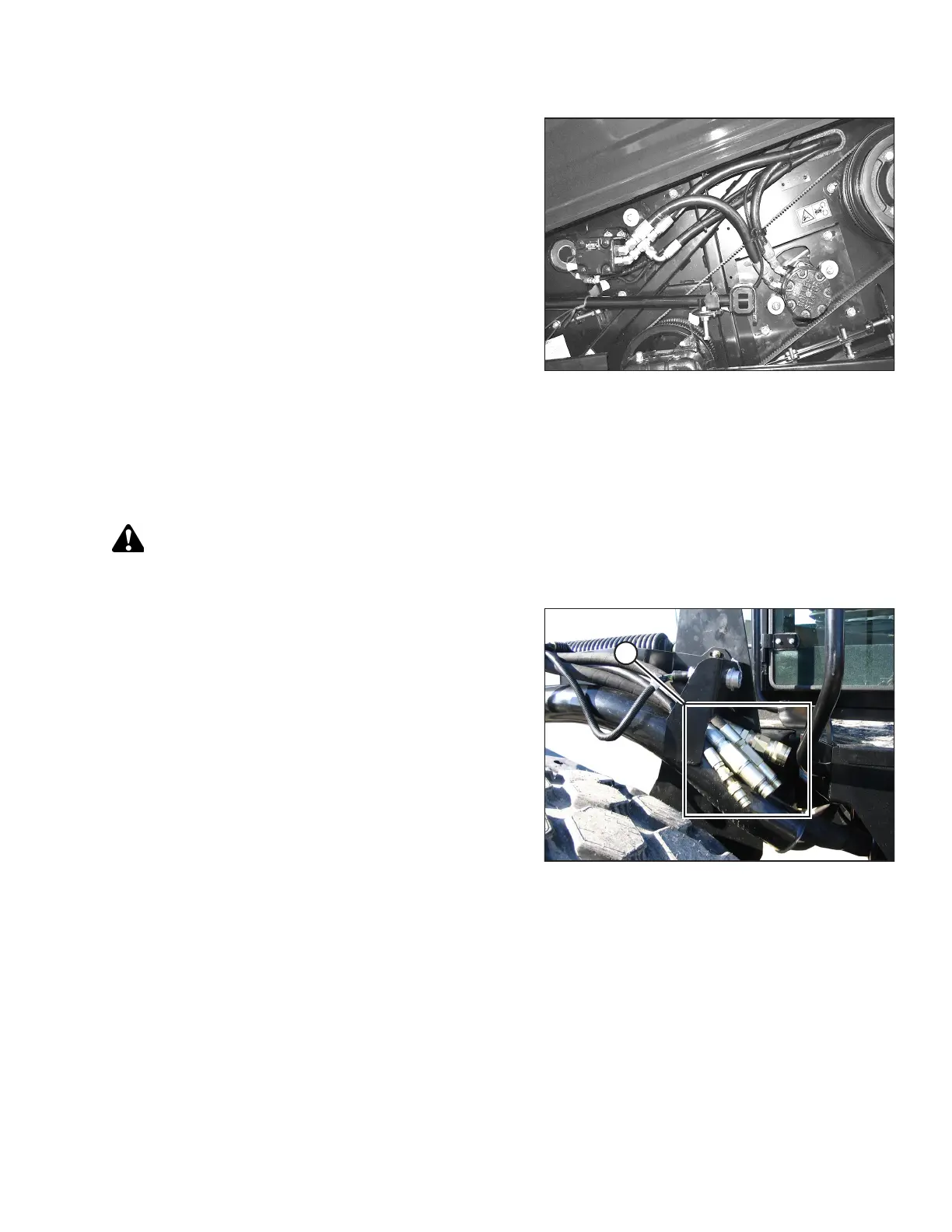
Figure 3.40: Header Drive Hoses
M150, M155, and M155 E4 Self-Propelled Windrowers are
factory-equipped with four header drive hoses (A) on the
left side.
1. Shut down the engine, and remove the key from the ignition.
OPERATION