262334 240 Revision A
O-Ring Boss Hydraulic Fittings – Non-Adjustable
The standard torque values for non-adjustable hydraulic fittings are provided. If a procedure specifies a different torque
value for the same type and size of fitting found in this topic, use the value specified in the procedure instead.
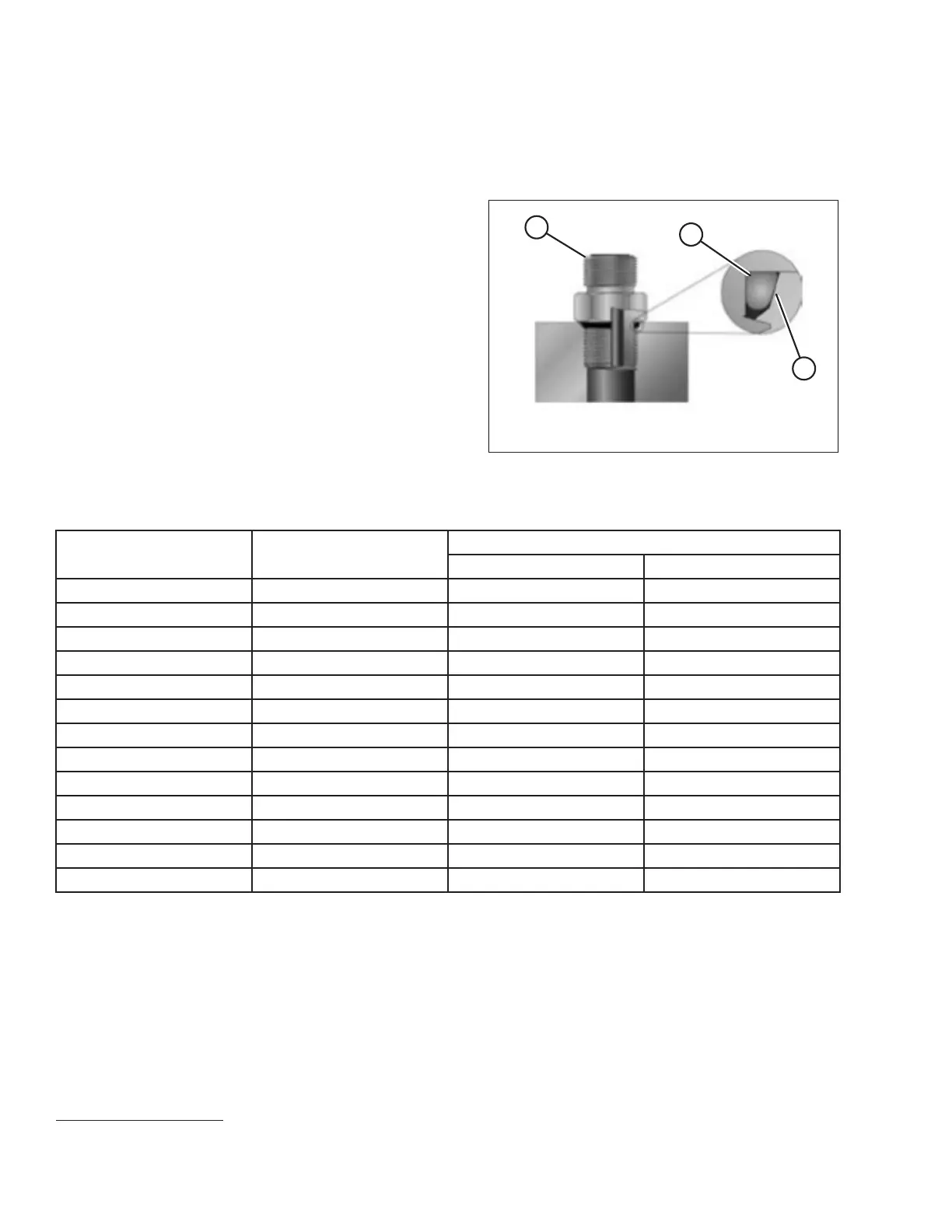
Figure 7.13: Hydraulic Fitting
1. Inspect O-ring (A) and seat (B) for dirt or defects.
2. Ensure that O-ring (A) is NOT on the threads. Adjust
O-ring (A) if necessary.
3. Apply hydraulic system oil to the O-ring.
4. Install fitting (C) into the port until the fitting is hand-tight.
5. Torque fitting (C) according to values in Table 7.12, page
240.
6. Verify the final condition of the fitting.
Table 7.12 O-Ring Boss (ORB) Hydraulic Fittings – Adjustable and Non-Adjustable
SAE Dash Size
Thread Size (in.)
Torque Value
8
Nm
lbf·ft (*lbf·in)
-2
5/16–24
10–11 *89–97
-3
3/8–24
18–20 *159–177
-4
7/16–20
29–32
21–24
-5
1/2–20
32–35 24–26
-6
9/16–18
40–44 30–32
-8
3/4–16
70–77 52–57
-10
7/8–14
115–127 85–94
-12
1 1/16–12
183–201 135–148
-14
1 3/16–12
237–261 175–193
-16
1 5/16–12
271–298 200–220
-20
1 5/8–12
339–373 250–
275
-24
1 7/8–12
414–455 305–336
-32
2 1/2–12
509–560 375–413
O-Ring Face Seal Hydraulic Fittings
The standard torque values are provided for O-ring face seal hydraulic fittings. If a procedure specifies a different torque
value for the same type and size of fitting found in this topic, refer to the value specified in the procedure instead.
Torque values are shown in the Table 7.13, page 241.
REFERENCE
8. Torque values shown are based on lubricated connections as in reassembly.