262334 239 Revision A
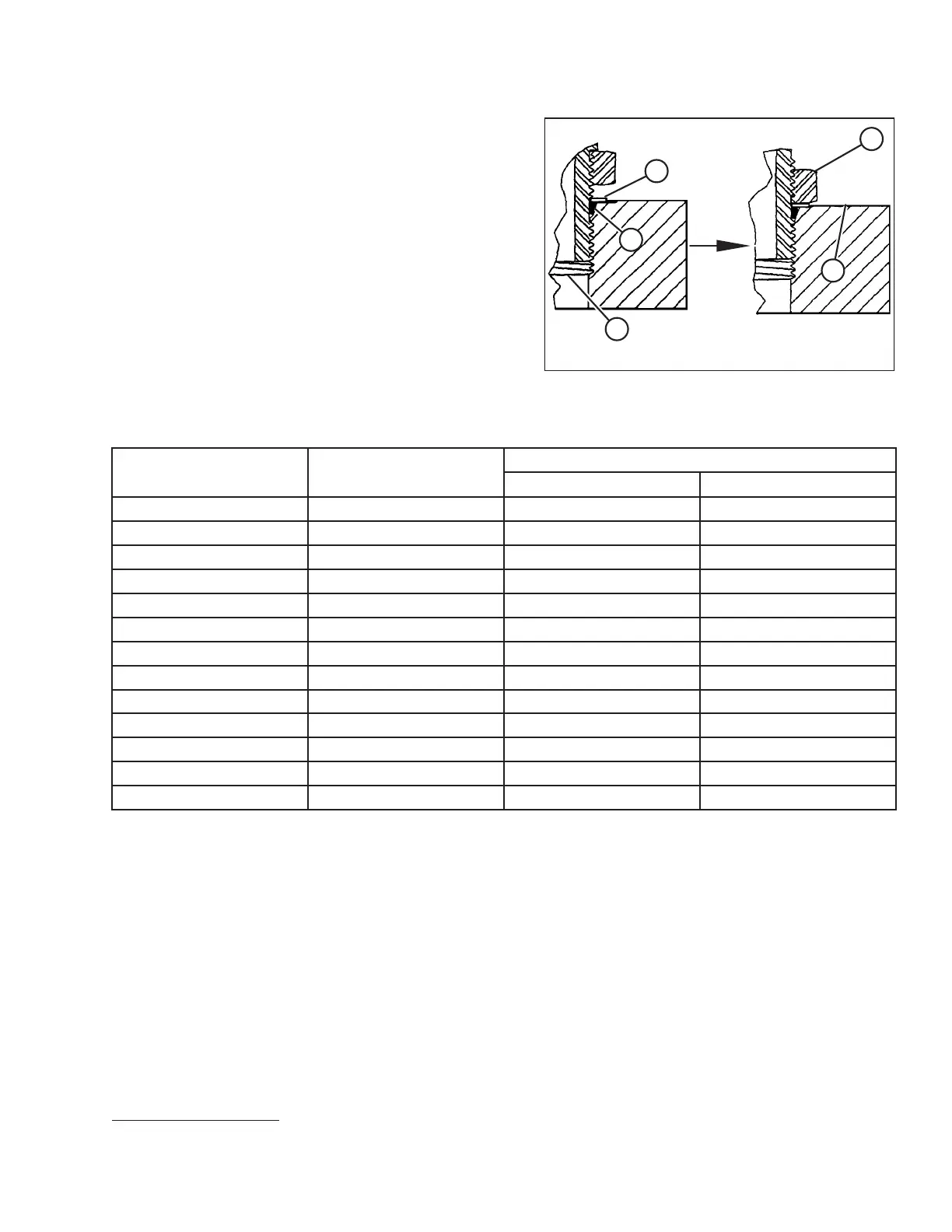
Figure 7.12: Hydraulic Fitting
5. Install fitting (B) into the port until backup washer (D) and
O-ring (A) contact part face (E).
6. Position the angle fittings by unscrewing no more than
one turn.
7. Turn lock nut (C) down to washer (D) and tighten it to the
torque value indicated in the table. Use two wrenches, one
on fitting (B) and the other on lock nut (C).
8. Verify the final condition of the fitting.
Table 7.11 O-Ring Boss (ORB) Hydraulic Fittings – Adjustable and Non-Adjustable
SAE Dash Size
Thread Size (in.)
Torque Value
7
Nm
lbf·ft (*lbf·in)
-2
5/16–24
10–11 *89–97
-3
3/8–24
18–20 *159–177
-4
7/16–20
29–32
21–24
-5
1/2–20
32–35 24–26
-6
9/16–18
40–44 30–32
-8
3/4–16
70–77 52–57
-10
7/8–14
115–127 85–94
-12
1 1/16–12
183–201 135–148
-14
1 3/16–12
237–261 175–193
-16
1 5/16–12
271–298 200–220
-20
1 5/8–12
339–373 250–
275
-24
1 7/8–12
414–455 305–336
-32
2 1/2–12
509–560 375–413
REFERENCE
7. Torque values shown are based on lubricated connections as in reassembly.