262334 202 Revision A
Figure 4.143: Forming Shield
5. Attach adjuster rods (B) to side deflectors (C) with lynch
pin (A).
4.14.5 Installing Forming Shield
Follow this procedure when installing the forming shield.
NOTE:
Forming shields are not compatible with narrow transport windrowers.
Figure 4.144: Triangular Plate
1. If attached, remove the header from the windrower for
ease of installing the forming shield. For instructions. refer
to the windrower operator’s manual.
NOTE:
Do NOT install the two triangular-shaped plates from the
forming shield kit. The triangular plates are used with
rotary headers only.
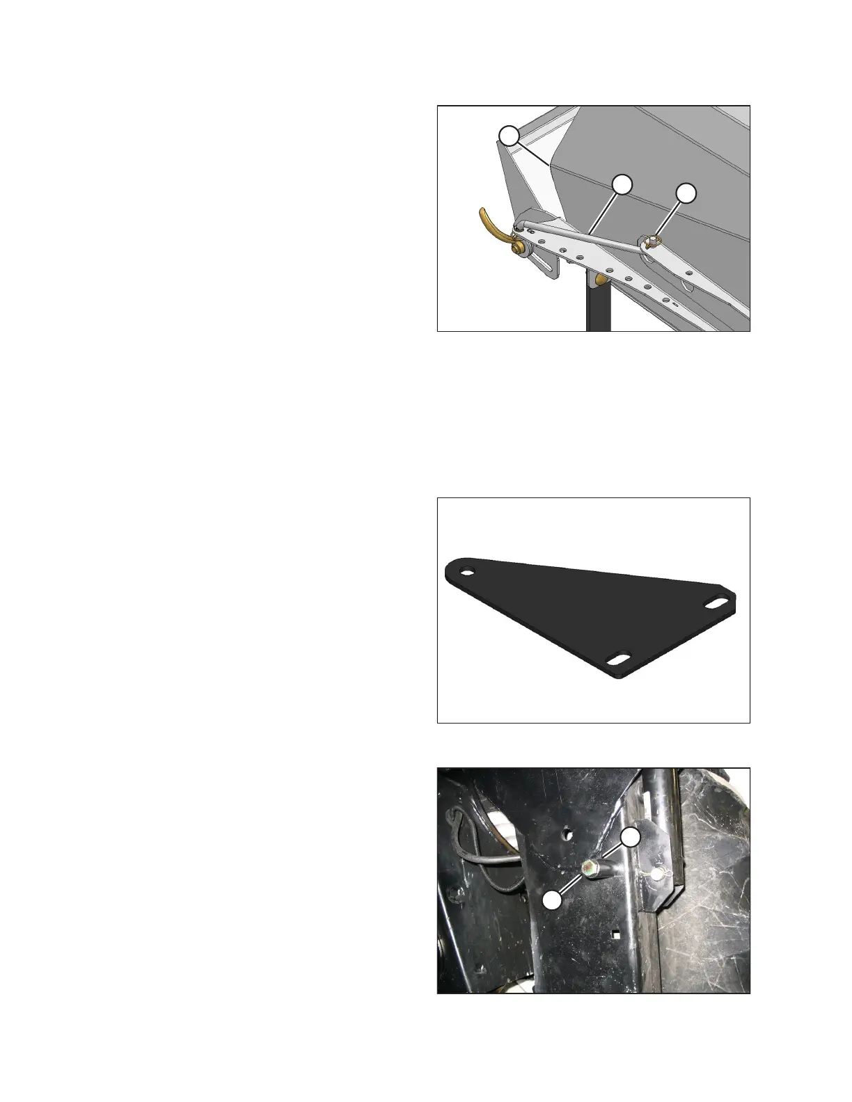
Figure 4.145: Windrower Leg
2. Install bolt (A) with spacer (B) and nut on each windrower
leg in the upper hole.
NOTE:
This hardware is supplied with the forming shield kit.
MAINTENANCE AND SERVICING