262334 64 Revision A
3.5.5 Configuring Reverser Valve Jumper Hose for A40D Auger Header
An optional reverser valve block may have been installed to reverse the header drive in the event of plugging on the M150,
M155, and M200 Self-Propelled Windrowers. A jumper hose on this valve block has a specific routing for each model of
header.
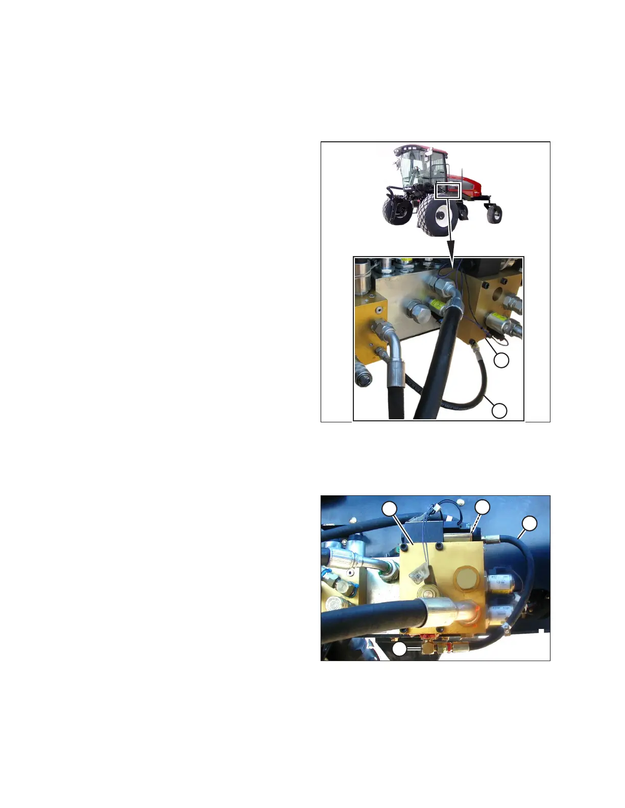
Figure 3.81: A40D Hose (B) Position (A40D on M200
Shown; M150, M155, and M155E4 Similar)
NOTE:
If a reverser valve block (A) has been installed, the jumper
hose (B) must be routed for the correct header model. Do NOT
operate the header unless the hose is routed as shown.
NOTE:
ONLY for draper headers with conditioner installed and ONLY for
the M150, M155, and M200 Self-Propelled Windrowers: CR is
routed to port R4 (not shown) on the reverser block. When
switching from draper header to auger header, jumper hose (B)
must be routed according to the header being operated to
prevent draper header reel damage and improper operation.
To reroute the jumper hose from the draper header position to A40D position, follow these steps:
Figure 3.82: Draper Header Hose Position (M150
Shown; M200, M155, and M155E4 Similar)
1. Move the left windrower platform to the open position to
expose the hydraulic valve blocks.
2. Disconnect jumper hose (B) from 90 degree fitting (C) at
port R4 on reverser valve block (A).
3. Rotate 90 degree fitting (D) under the reverser valve block
so that the hose can be routed to port C2 at (C) as shown in
Figure 3.83, page 65.
OPERATION