262334 63 Revision A
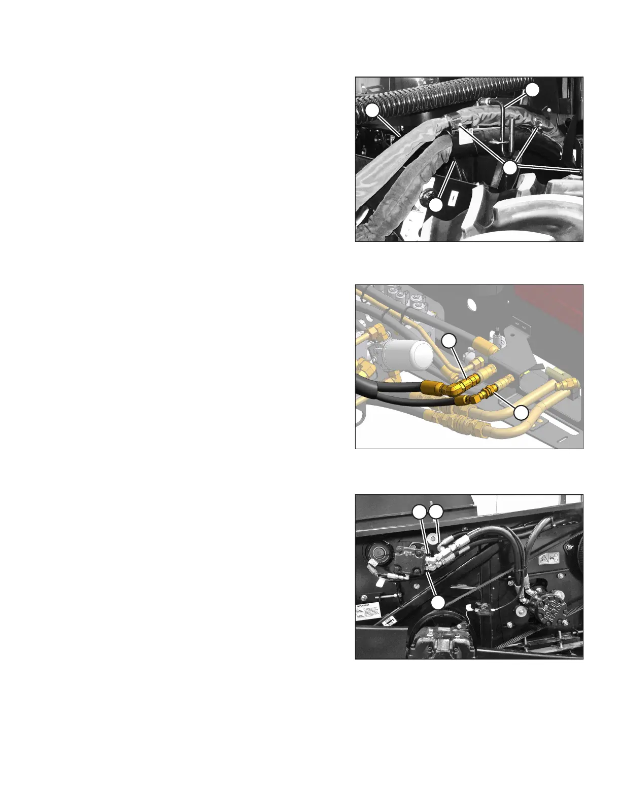
Figure 3.78: Auger Return and Reel Pressure
Hose Bundle
14. Route auger return/reel pressure hose bundle (A) from the
header to the windrower, and position the bundle above
existing hose support (C) as shown.
15. Secure the bundle with three straps (D), and lower
lever (B).
Figure 3.79: Auger/Reel Pressure and Auger/Reel
Return Hose Couplers
16. Push auger/reel pressure (A) and auger/reel return (B) hose
couplers onto the mating receptacles on the manifold until
the collar on the receptacle snaps into the lock position.
Figure 3.80: A40D/A40D GSS Header – Factory
Configuration for M150, M155, M155E4 and M200
17. Check reel pressure line (A) connection to the reel drive
motor (B). Connect the reel pressure line to a different port
on the reel motor port depending on the model of
windrower:
• If attaching the header to an M150, M155, M155E4, or
M200, do NOT change the reel pressure connection to
the motor, UNLESS switching to windrower models
M100, M105, or M205. All model years of A40D / A40D
GSS are factory-configured for M150, M155, M155E4,
and M200.
• Before attaching the header to an M100, M105, or
M205 move the reel pressure line connection (A) to the
other port (C). Refer to 3.5.6 Routing A40D Auger
Header Hydraulic Drive Hoses, page 65.
OPERATION