262334 65 Revision A
Figure 3.83: Connected Jumper Hose
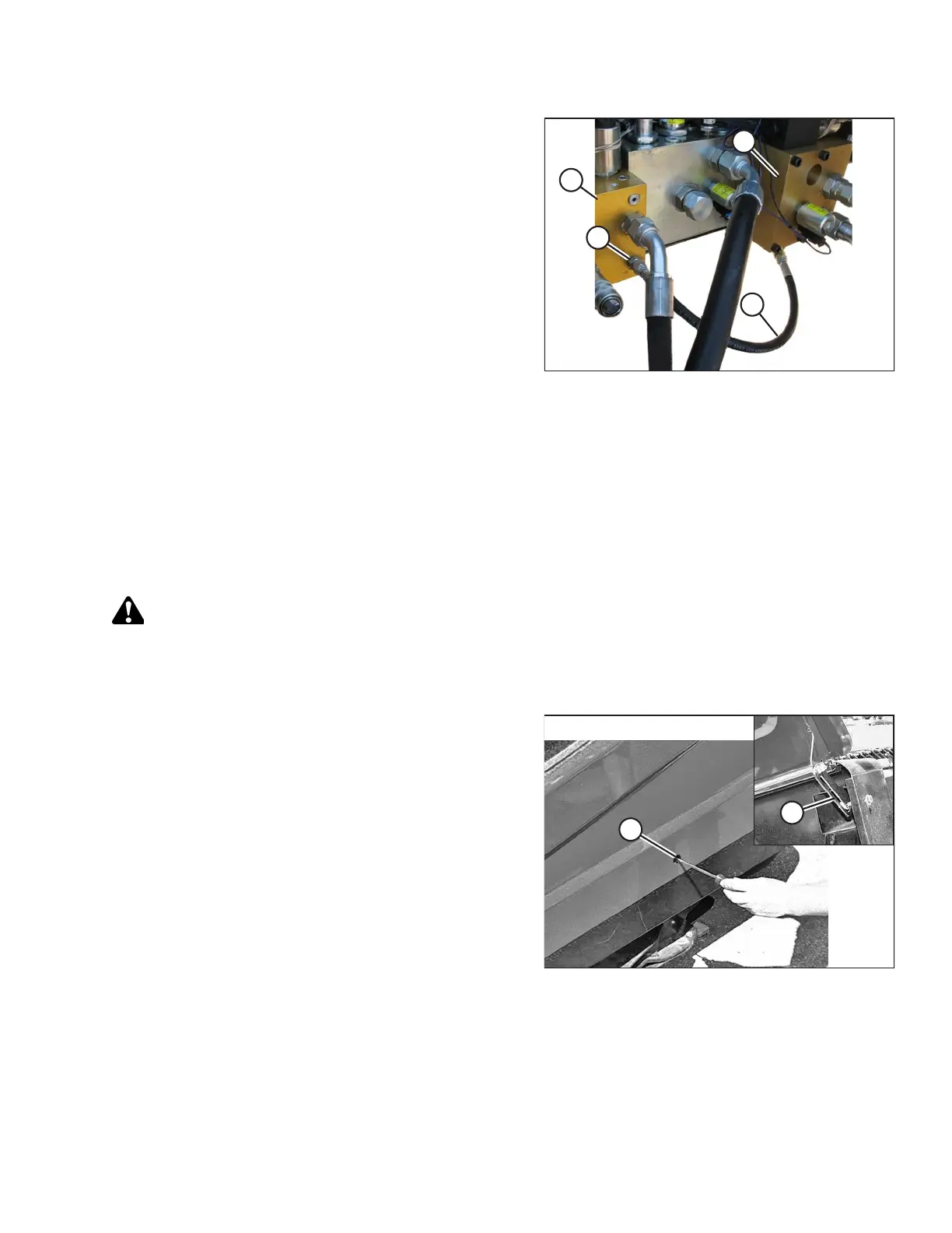
4. Remove the cap from port C2 fitting (A) on header drive
valve block (B).
5. Connect jumper hose (C) to port C2 fitting (A) on header
drive valve block (B).
6. Install the previously removed cap onto the 90 degree
fitting in port R4 on reverser valve block (D).
7. Move the left windrower platform back to the normal
operating position.
NOTE:
The draper header reverser function is suppressed unless
the hay conditioner is activated in Windrower Setup using
the cab display module (CDM).
3.5.6 Routing A40D Auger Header Hydraulic Drive Hoses
The A40D Auger Header hydraulic drive hose routing depends on the windrower model to which the header is being
attached.
A40D Headers are factory-configured for M150, M155, M155E4, and Self-Propelled M200 Windrowers as shown in
Figure 3.90, page 68.
To route hoses for M100, M105, and M205 Self-Propelled Windrowers, proceed as follows:
DANGER
To prevent injury or death from the unexpected start-up of the machine, always stop the engine and remove the key
from the ignition before leaving the operator’s seat for any reason.
1. Shut down the engine, and remove the key from the ignition.
Figure 3.84: Left Endshield
2. Press a screwdriver against the latch in opening (A) and lift
it to open the header left endshield. The shield will latch at
location (B) to stay open.
OPERATION