262334 46 Revision A
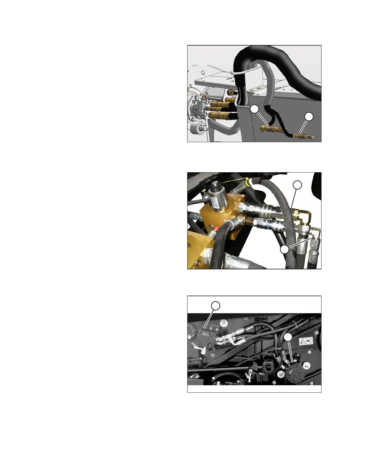
Figure 3.36: Auger/Reel Pressure and Auger/Reel
Return Hose Couplers – 4.3 m and 4.9 m (14 ft. and
16 ft.) Header Shown (5.5 m [18 ft.] Header Similar)
Figure 3.37: Auger/Reel Pressure and Auger/Reel
Return Valve Block Receptacles
16. Push auger/reel pressure (A) and auger/reel return (B) hose
couplers onto the mating receptacles on the valve block
until the collar on the receptacle snaps into the lock
position.
Figure 3.38: Factory Routing M150, M155, and M200
A - Reel Motor B - Auger Motor
17. Check the hose routing at the reel motor.
NOTE:
The hose routing depends on which windrower model the
header is being attached to. The header is factory
configured for M150, M155, M155E4, and M200
Self-Propelled Windrowers.
OPERATION