262334 31 Revision A
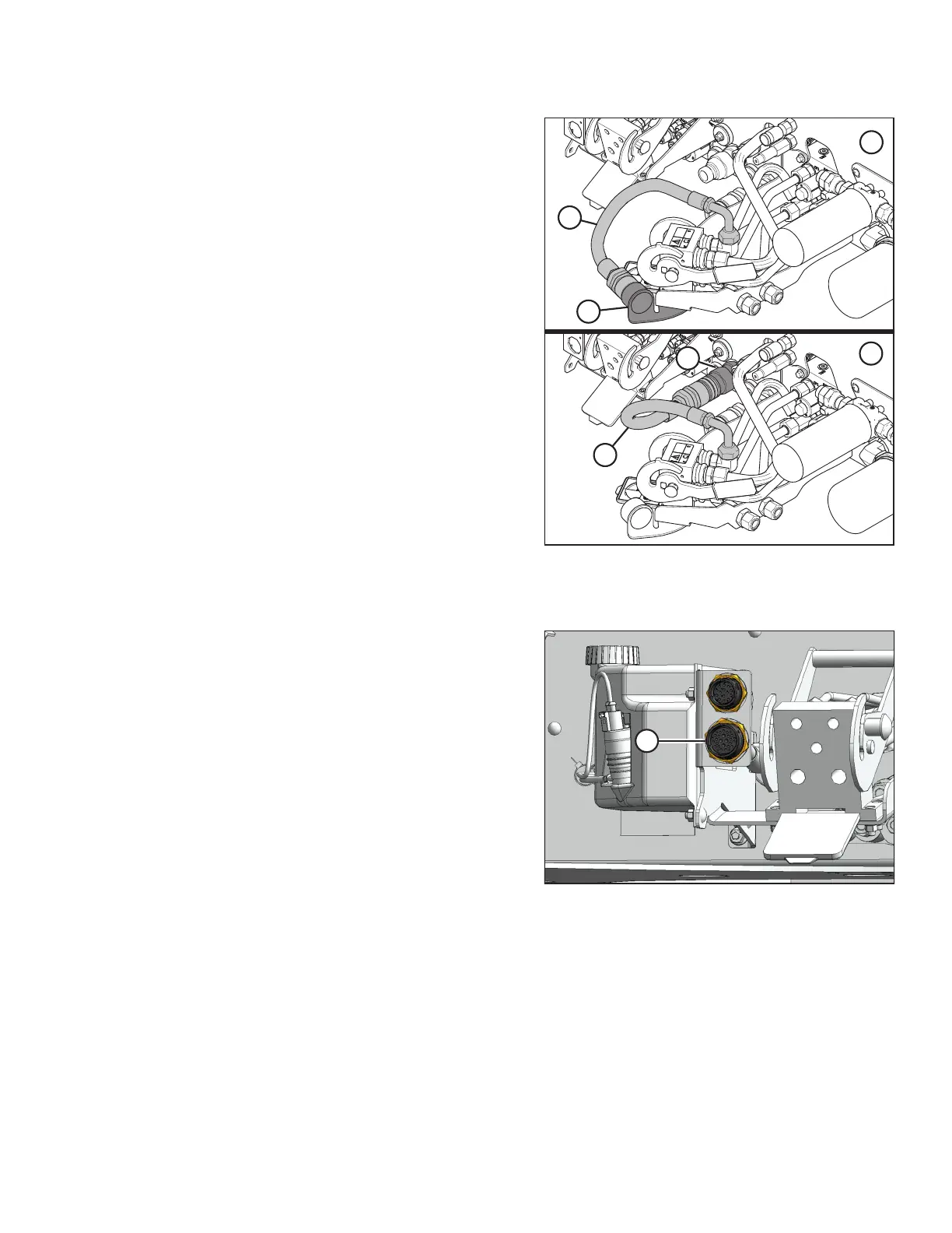
Figure 3.5: Knife Pressure Hose Positions
1 - Hose in Storage Position (Rotary Configuration)
2 - Hose to Knife Pressure Receptacle (Auger/Draper Configuration)
12. If a rotary disc header is being replaced by an auger
header: Remove hose (A) from storage location (B).
Connect hose (A) to knife pressure receptacle (C) on
the frame.
NOTE:
Hose quick disconnect (C) is present only on the following
configurations:
• M2170 Windrowers equipped with the R1 Series
Hydraulic Drive kit (B6845)
• M2260 Windrowers configured for draper or auger
headers
Figure 3.6: Electrical Connectors
13. Remove the cover from receptacle (A). Connect the
header’s electrical harness to the receptacle.
OPERATION