262334 55 Revision A
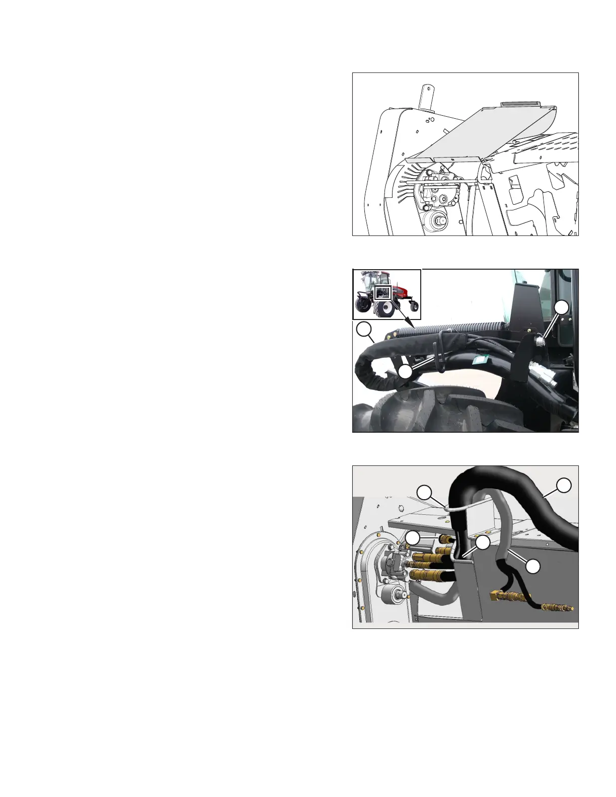
Figure 3.58: Driveshield Open
The driveshield is shown in the open position.
Figure 3.59: Support Bracket and Hose Bundle
4. Remove cap (A) from the electrical connector, and remove
the connector from the support bracket.
5. Disengage and rotate lever (B) counterclockwise to the
raised position to release hose bundle (C).
Figure 3.60: Hose and Electrical Bundle – 4.3 m and
4.9 m (14 ft. and 16 ft.) Header Shown (5.5 m [18 ft.]
Header Similar)
6. Move hose/electrical bundle (A) to the header.
7. Route bundle (A) from the windrower through support (B)
and access hole (C) in the header frame alongside existing
hose bundle (D) from the header.
8. Remove the cover on header electrical receptacle (E).
9. Push the connector onto the receptacle, and turn the collar
on the connector to lock it in place.
10. Attach the cover to the mating cover on the windrower
wiring harness.
11. Remove the caps from the hydraulic couplers. Clean them if
necessary.
OPERATION