Installation
2-66 Manual # 42-02-2P24
Parameter Settings
Please refer to “Hoistway Learn, LS-EDGE” on page 3-5 for hoistway learn, slowdown learn,
and ETS placement instructions.
Permanent Magnet Attachment
Once the hoistway has been successfully learned and magnet placement is satisfactory, you may
“lock” the magnets in place by placing a drop of silicone adhesive immediately above the top
end and immediately below the bottom end of each magnet.
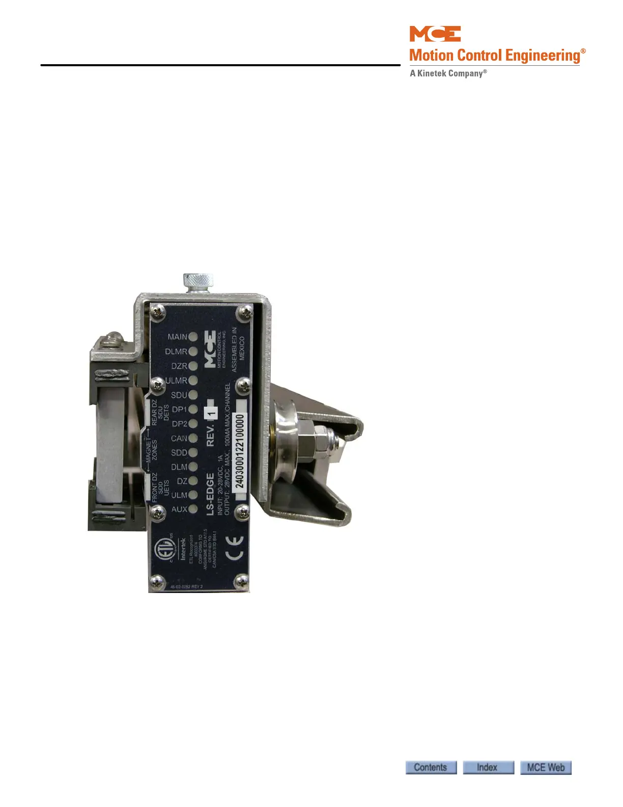
Indicators
Lighted indicator LEDs on top of the sensor unit provide information about active signals.
Figure 2.23 Indicator LEDs
• DP1, DP2: Quadrature pulses (iControl). DP1 leads when the car is traveling up. DP2 leads
when the car is traveling down. Alternately active whenever the car is in motion.
• CAN: Motion 4000 CAN communication with landing system is active.
MAIN: Sensor processor A active.
DLMR: Down Level Marker Rear.
DZR: Door Zone Rear.
ULMR: Up Level Marker Rear.
SDU: Slow Down Up.
DP1:Quadrature pulse.
DP2: Quadrature pulse.
CAN: CAN communication activity.
SDD: Down Slow Down.
DLM: Down Level Marker (Front).
DZ: Door Zone (Front).
ULM: Up Level Marker (Front).
AUX: Sensor processor B active.