Installation
2-82 Manual # 42-02-2P24
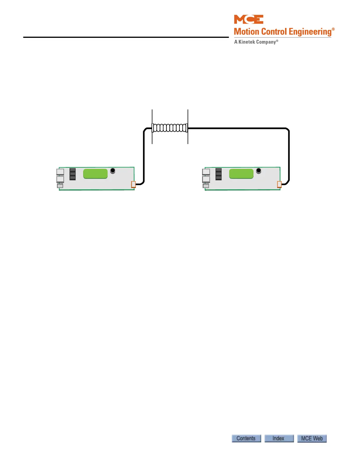
Duplex Connection Between Controllers
If you are installing controllers in a duplex configuration, you must connect a communication
cable between the two as shown in your job prints. Jumper JP3 (terminates the CAN bus) must
be in place on each HC-MPU board. The controls must also be set up in software to operate as a
duplex installation (F1, Program Mode).
Figure 2.32 Typical Duplex Communication Connection
Hall Calls, Position Indicators, and Peripherals
Motion 4000 hall calls may use discrete call connections or optional CAN Bus connections.
Please refer to “Hall Call Node Wiring” on page 5-73 if you have serial hall calls.
1. Install hall calls, position indicators, and peripherals (auxiliary risers, etc.) according to
building requirements and pertinent local and national codes.
2. Install access switches in hall ways in accordance with drawings package.
3. Connect hall switches, push buttons, and indicator lamps or LEDs as shown in the MCE
job prints.
CE Position Indicators
CE Electronics position indicators are supported using a CE driver board in the controller. The
driver board connects to the controller internal CAN bus. A transformer provides 24-volt power
to the board. The three-wire CE output (1= common, 2= fixture power, 3= data) is typically
brought to panel mount terminals (RD1, RD2, RD3) for easy access. Refer to the MCE drawings
package and to the CE documentation provided with your fixtures.
RS232 (x3)
Keyboard
Main Processor (HC-MPU)
LCD
RS232 (x3)
Keyboard
Main Processor (HC-MPU)
LCD
Conduit
Controller A Controller B