Troubleshooting
5-58 Manual # 42-02-2P24
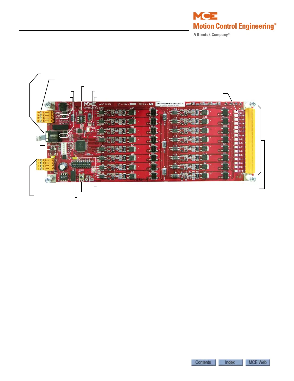
HC-UIO Universal Input/Output Board
Depending upon the software installed, HC-UIO boards may be used for programmable inputs
and outputs (16 per board), car and hall calls, door operator interface, or dispatching.
Figure 5.7 HC-UIO Universal Input/Output Board
Switches
•DIP SW1:
• Switches 1 through 6 = Board ID (see “HC-UIO Board Call Assignments” on page 5-59)
and (see “HC-UIO Spare Input / Output Assignments” on page 5-61)
•Switches 7 & 8 = Baud rate (see “HC-UIO Board DIP SW1 Switches 7 and 8” on page 5-
60)
• Switch 9 = Input levels (see “HC-UIO Board DIP SW1 Switch 9 for I/O Boards” on
page 5-60)
• Sw2: RST - Processor reset
Jumpers
• JP2: Internal CAN Network Termination
• JP3: External CAN Network Termination
• JP6: Selects voltage reference
• A = 120Vac power supplied by J4 (default)
• B = 24Vdc power supplied by CAN bus
Test Points
• GND: Digital Ground - 0 V
• +5V: +5 Vdc measured between this test point and TP GND.
• 1: 1 Bus (common)
J7: External CAN connection
J2: Internal CAN connection
J4
J3:24 - 120V AC or DC Inputs / Outputs
Indicators
JP3
JP2
JP6
TP GND
CPU ON LED
SW1
TP1
SW2: RST
J1
TP +5V