Troubleshooting
5-40 Manual # 42-02-2P24
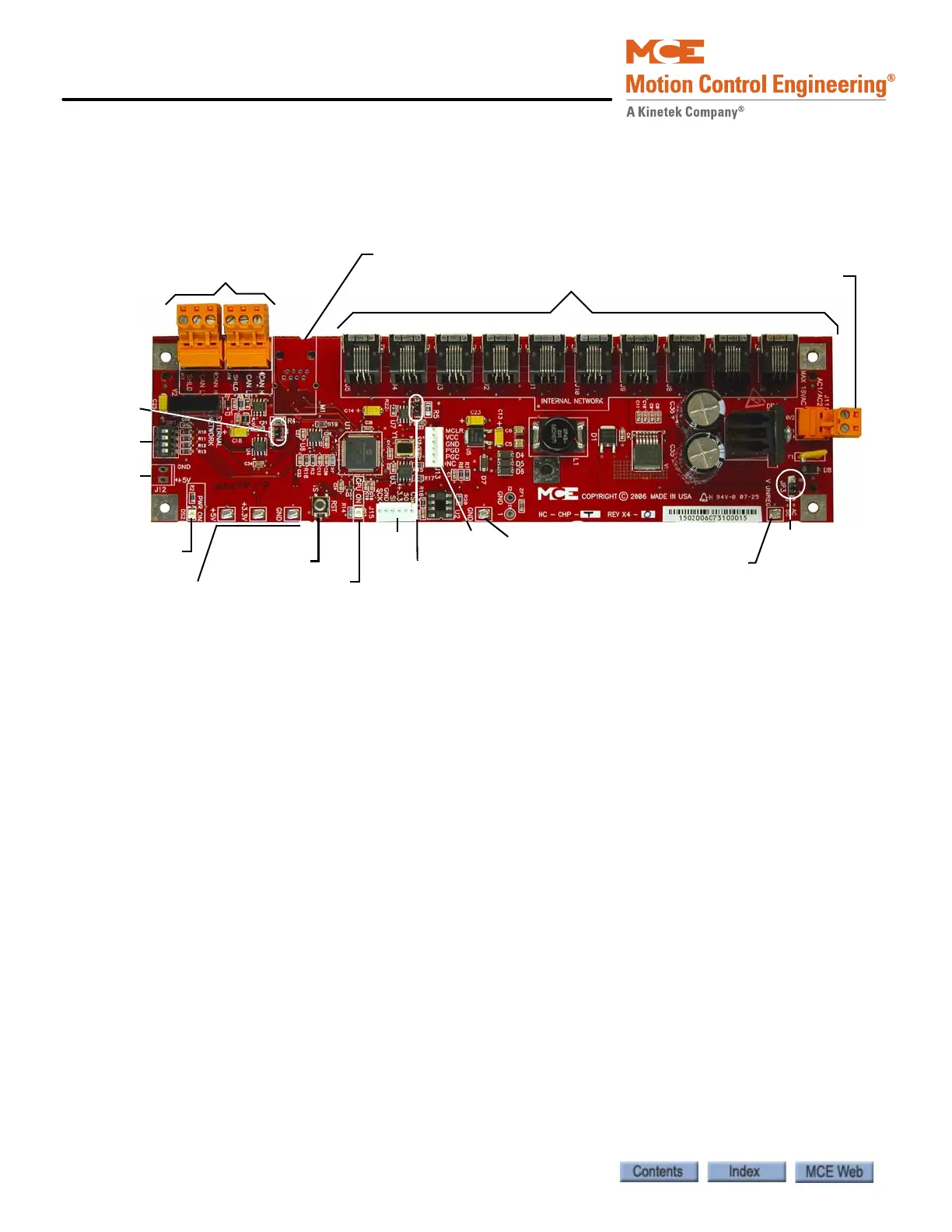
HC-CHP CAN Hub and Power Supply Board
This board provides 4-amp power for boards throughout the controller and a central connection
point for the Controller Area Network (CAN).
Figure 5.2 HC-CHP CAN Hub and Power Supply Board
Connectors
• J1 - J10: Network connections to boards inside the controller cabinet.
• J11: Low voltage AC input - 16V1/16V2, maximum 18Vrms.
• J12: Optional +5Vdc output.
• J13: Serial programming port for microcontroller.
• J15: Interface to external memory.
• J16, J17: External CAN network connections to boards or equipment outside the cabinet.
• M1: Optional Ethernet connection.
Jumpers
• JP1: Internal CAN bus termination resistor.
• JP2: External CAN bus termination resistor.
• JP3: Sets pick-off point for power failure detection. Factory use only.
Default is A= Direct AC monitoring.
Test Points
• +5V: +5Vdc measured between this test point and TP GND.
• +3.5V: +3.3Vdc measured between this test point and TP GND.
•GND: 0V.
•V UNREG: 24V A20% measured between this test point and TP GND.
J11: AC input
18 Vrms max.
J1 - J10: Internal Network connections
J16, J17 External
Network connections
M1:Optional Ethernet connection
SW1
J12
PWR ON LED
Test Po i n t s
+5V, +3.3V, GND
RST button
CPU ON LED
J15
TP GND
JP2
J13
JP3
JP1
TP V UNREG