F5 Menus
4-111
4
Motion 4000
System CAN Bus
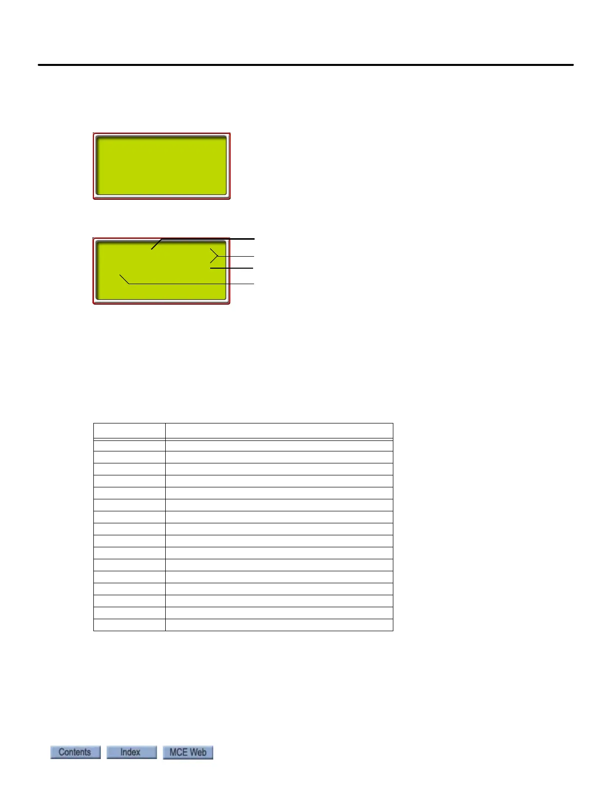
The System CAN Bus/Data Viewing screen allows you to check the working status of the inputs
and outputs of any Car Panel Interface board in the system.
• Press S to enter the menu
• Use the + or - buttons to increment/decrement address digit value
• Use the S button to move from digit to digit
• As soon as a valid ID is on the screen, the CAN data from that ID will be visible as the
hex data for each CAN byte changes.
• With the desired ID selected, you can place a call from the affected control panel, or
press a Door Open button, etc. and view the data transfer on the CAN bus.
If CAN data is not appearing: Please refer to “Status and Error Messages” on page 5-3, entry
“
MPI A or B LANDING SYSTEM COMM LOSS” for relevant CAN connection car-to-controller
troubleshooting information.
Table 4.16 MC-CPI Board Addresses
ID DATA
1C0 Output activity CPI board “0”
1C1 Input activity CPI board “0”
1C2 Output activity CPI board “1”
1C3 Input activity CPI board “1”
1C4 Output activity CPI board “2”
1C5 Input activity CPI board “2”
1C6 Output activity CPI board “3”
1C7 Input activity CPI board “3”
1C8 Output activity CPI board “4”
1C9 Input activity CPI board “4”
1CA Output activity CPI board “5”
1CB Input activity CPI board “5”
1CC Output activity CPI board “6”
1CD Input activity CPI board “6”
1CE Output activity CPI board “7”
1CF Input activity CPI board “7”
SYSTEM CAN BUS
*DATA VIEWING*
CID| 00 00 00 00
1C1| 0A 10 00 01
CAN Data Bytes in Hex
Three digit MC-CPI address (see table below)
Byte 0
Byte 7