Landing/Positioning System
2-61
2
Motion 4000
Sensor Alignment
After the tape has been installed, check the sensor alignment. The sensor should not ride hard
on either side of the uni-strut bracket during any part of travel through the hoistway. In high-
rise buildings, if rail alignment varies substantially, it may cause the encoder guides to wear
prematurely. If such misalignment is noted, the installation should be inspected more regularly.
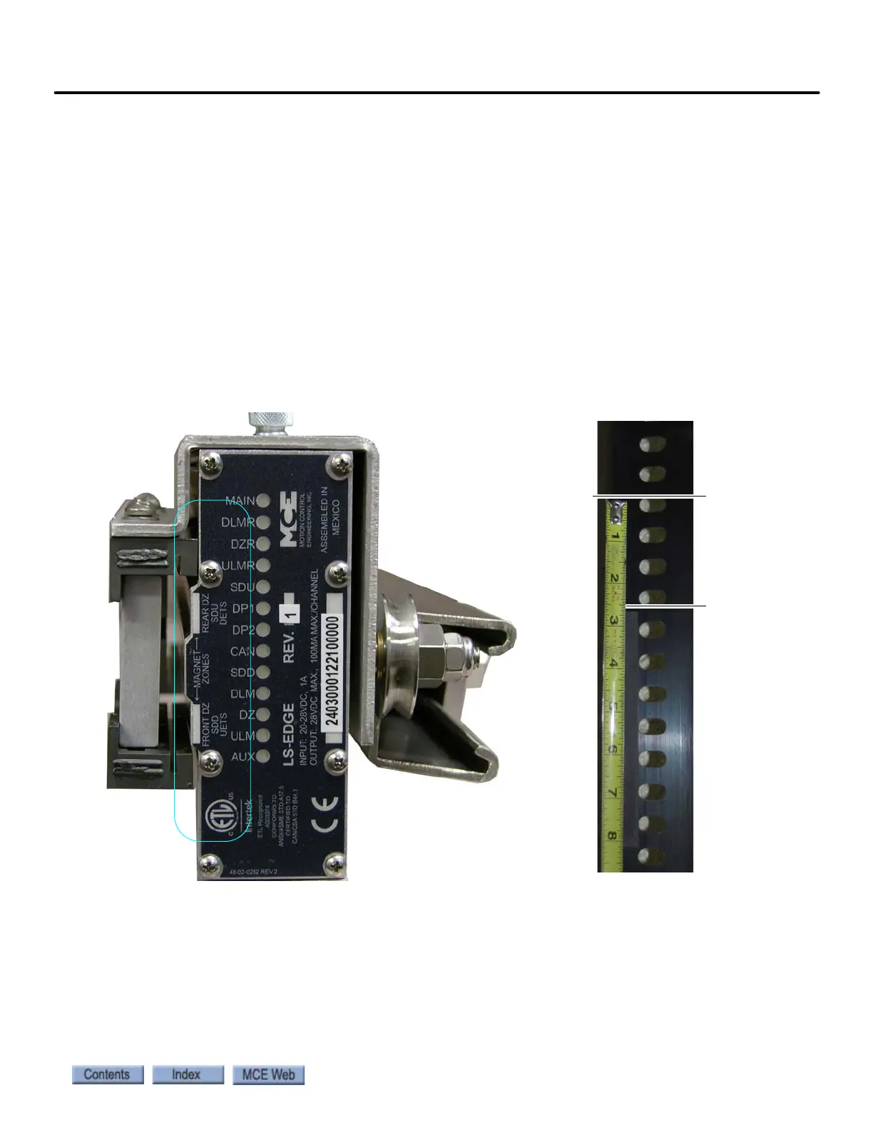
Door Zone, Terminal, and ETS Magnets
5.5-inch strip magnets are used at each floor/opening position. Front and rear magnet align-
ment is shown on the sensor top label. Looking at the perforated tape from the elevator car, the
magnets for the front door zone are mounted to the left of the perforated holes; magnets for the
rear door zone are mounted to the right of the holes. For Motion 4000 installations, special
magnets marked with a stripe are used at the top and bottom terminals and for ETS magnets if
used.
Figure 2.19 Door Zone Magnet Alignment
Scribe
Line
Top o f
Magnet
2 5/8
inches