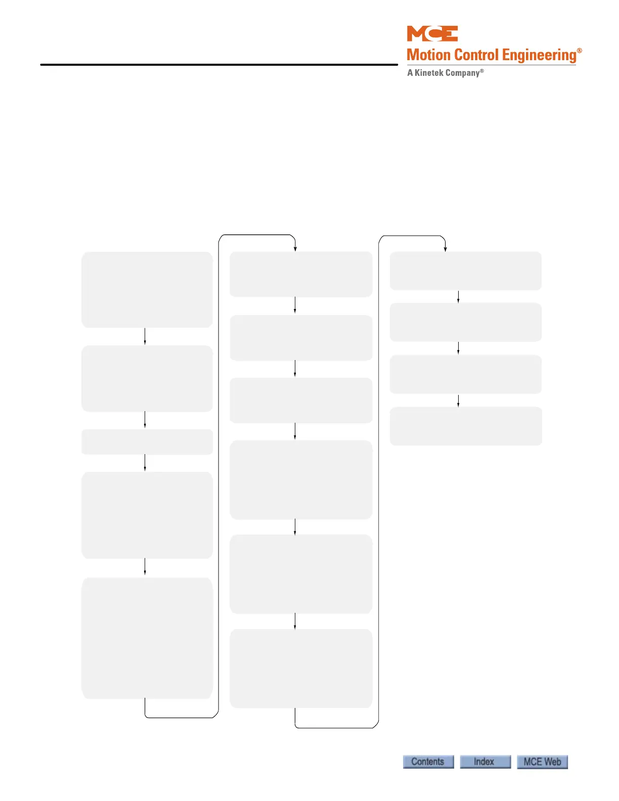
A1 Drive menu
Contract Car Speed
Contract Motor Speed
Brake Pick Time 0.0
Encoder Pulses
Mtr Torque Limit
Regen Torq Limit
A2 S-Curves menu
Accel Rate 0 0.00
Decel Rate 0 0.00
Accel Jerk Out 0 0.00
Decel Jerk In 0 0.00
Decel Jerk Out 0 0.00
A4 Power Convert menu
Input L-L Volts
A5 Motor Menu
Motor ID (4 or 6 pole)
Rated Mtr Power
Rated Mtr Volts
Rated Excit Freq
Rated Motor Curr
Motor Poles
Rated Mtr Speed
C1 User Switches menu
Spd Command Src Serial
Run Command Src Serial
Spd Reg Type Elev Spd Reg
Cont Confirm Src External
Pre-Torque Source Serial
Fault Reset Src Serial
Ramped Stop Sel Ramp On Stop
Ramp Down En Src Run Logic
Motor Ovrld Sel Fault At Stop
Serial Mode Mode 1
HPV900: C4 Analog Outputs menu
Analog Output 1 (TB1-33) Speed Command
Analog Output 2 (TB1-35) Speed Feedback
HPV900II: C4 Analog Outputs menu
Analog Output 1 (TB2-1) Speed Command
Analog Output 2 (TB2-8) Speed Feedback
HPV600: C4 Analog Outputs menu
Analog Output 1 (A0-A1) Speed Command
Analog Output 2 (A0-A2) Speed Feedback
HPV600PM: C4 Analog Outputs menu
Analog Output 1 (TB6-A01) Speed Command
Analog Output 2 (TB6-A02) Speed Feedback
900/900PM: C2 Logic Inputs menu
Logic Input 1 (TB1-1) Drive Enable
Logic Input 2 (TB1-2) Contact Cfirm
Logic Input 3 - 9 No Function
900II: C2 Logic Inputs menu
Logic Input 1 (TB1-6) Drive Enable
Logic Input 2 (TB1-7) Contact Cfirm
Logic Input 3 - 9 No Function
600/600PM: C2 Logic Inputs menu
Logic Input 1 (TB1-16) Drive Enable
Logic Input 2 (TB1- 7) Contact Cfirm
Logic Input 3 - 9 No Function
900/900PM: C3 Logic Outputs menu
Logic Output 1 (TB1-14) Ready To Run
Logic Output 2 (TB1-15) Run Commanded
Logic Output 3 (TB1-16) Speed Reg Rls
Logic Output 4 (TB1-17) Ramp Down En
Relay Coil 1 (TB2-51/52/53) Ready to Run
Relay Coil 2 (TB2-54/55/56) Speed Reg Rls
900II: C3 Logic Outputs menu
Logic Output 1 (TB1-13) Ready To Run
Logic Output 2 (TB1-14) Run Commanded
Logic Output 3 (TB1-15) Speed Reg Rls
Logic Output 4 (TB1-16) Ramp Down En
Relay Coil 1 (TB2-27/28/29) Ready to Run
Relay Coil 2 (TB2-30/31/32) Speed Reg Rls
600/600PM: C3 Logic Outputs menu
Logic Output 1 (TB1-9) Ready To Run
Logic Output 2 (TB1-10) Run Commanded
Logic Output 3 (TB1-11) Speed Reg Rls
Logic Output 4 (TB1-12) Ramp Down En
Relay Coil 1 (TB2-51/52/53) Ready to Run
Relay Coil 2 (TB2-54/55/56) Speed Reg Rls