PC Board Quick References
5-63
5
Motion 4000
Normal Operation
During normal operation, I/O LEDs will be lighted when the associated I/O is active (dimmer
when the output is active; brighter when the input is active). The SPA processor LED will be
continuously lighted. If I/O LEDs remain in a static condition or the SPA processor LED is not
continuously on:
• Press the RST button on the board. The I/O LEDs will all cycle and the board will resume
operation.
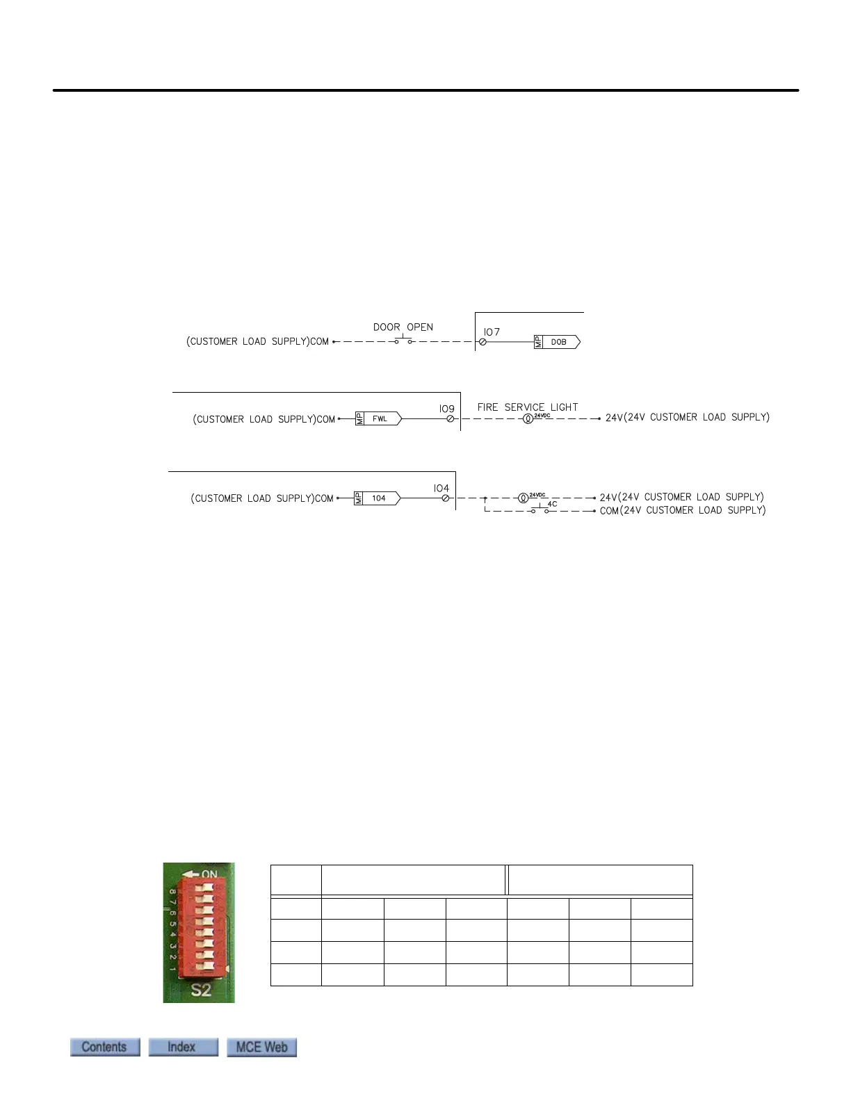
ICE-COP-2 Board Details
• 24V Inputs Only: Typical circuit for terminals I1 through I16.
• 24V Outputs Only: Typical circuit for terminals O1 through O16.
• 24V Inputs/Outputs Only: Typical circuit for terminals
IO1 through IO16.
S2 Switches Eight-position DIP switch S2 allows a unique address to be set for each
COP board, places the board in CAN or iControl communication mode, sets the board input
threshold, and determines the CAN baud rate (when CAN is enabled). See “Factory I/O Assign-
ment, ICE-COP-2 Boards” on page A-29.
• RS485 or CAN Communication
• For Motion controls, the board must be set to use CAN communication.
• CAN Enable: Verify/set switch 8 to the ON position.
• Motion Input Threshold Detection
On COP-2 boards with software version 1.1 or later, the input threshold level may be set to
900 or 700mV using DIP switch rocker 5.
• Board revision X2-1 or greater: Recommended, rocker 5 OFF: 900mV (default)
• Board revision X2-0: Recommended, rocker 5 ON: 700mV
• Motion Board Addressing
For Motion controls, each COP-2 board used must have a unique address.
• Addressing - switches 1, 2, and 3:
S2
Front COP Boards Rear COP Boards
Board SW1 SW2 SW3 SW1 SW2 SW3
1 Off Off Off Off Off On
2 On Off Off On Off On
3 Off On Off Off On On