Troubleshooting
5-64 Manual # 42-02-2P24
•Motion CAN Baud Rate
• Switch 7 OFF: 250k (default)
• Switch 7 ON: 500k
• Motion Unused Switches
• Switches 4 and 6 are unused and should be left in the OFF position.
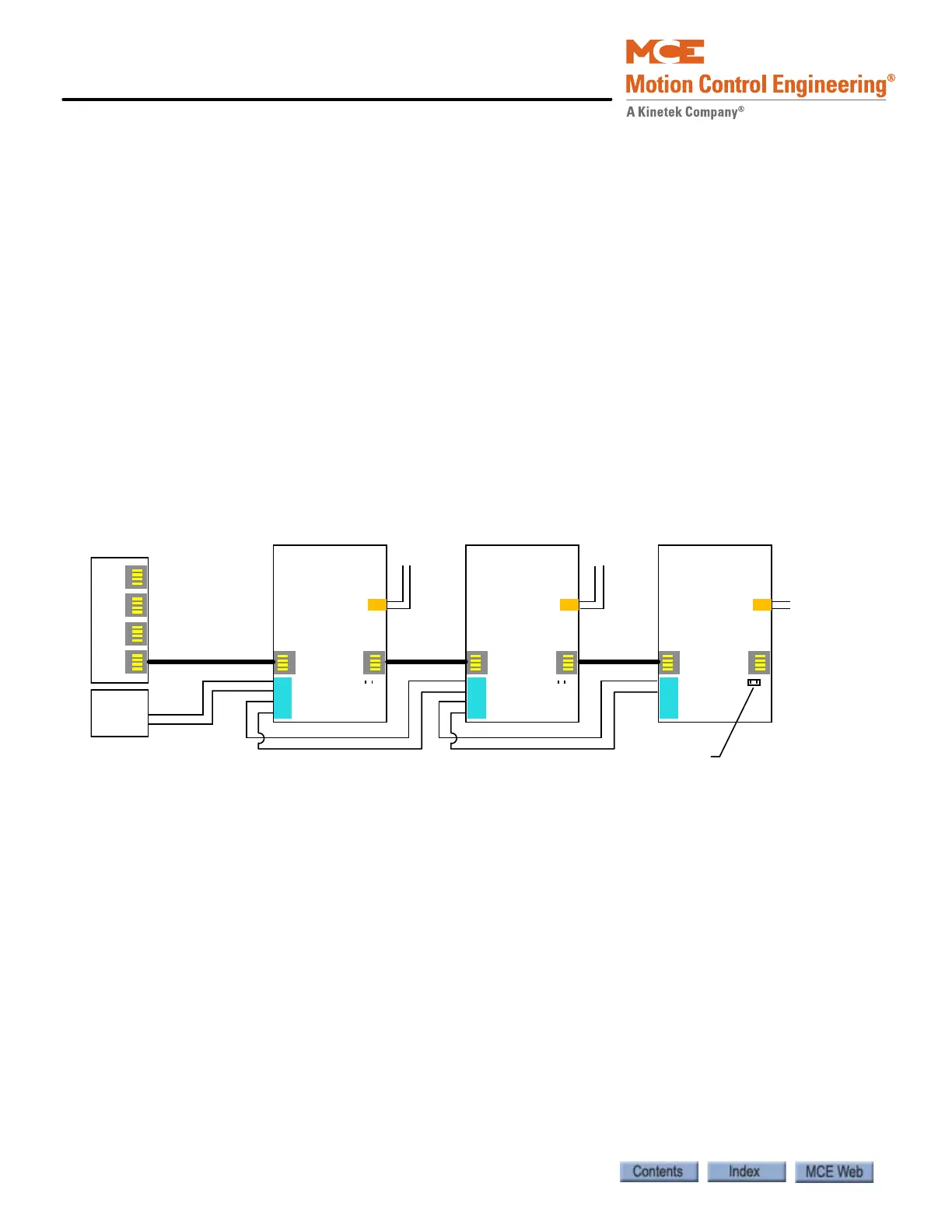
• 24V Power: The 24V power supply from the cartop box must be connected to the 24V IN
connector J35 on the first ICE-COP-2 board. If additional boards are used, they are con-
nected to 24V as shown in “ICE-COP-2 Board Interconnect” on page 5-64. Load connec-
tions (power source for buttons and switches in the car panel) can be made to any of the
boards at the 24V CUSTOMER LOAD SUPPY connector as long as load current at any one
board is not more than 4A.
• CAN Bus termination: Jumper JP1 terminates the CAN bus in the correct impedance
for CAN signal transmission.
• If more than one COP board is used, ONLY the last board in the CAN string should
have jumper JP1 plugged in. (If there is only one COP board, it must have JP1 plugged
in.)
Figure 5.8 ICE-COP-2 Board Interconnect
COP Board #1
Address: 0 (S2)
J31
J32
JP1
+V
Com
+V
Com
COP Board #2
Address: 1 (S2)
J31 J32
JP1
COP Board #3
Address: 2 (S2)
J31 J32
JP1
LSI Board
On Cartop
24V
Power
Supply
C-RJ11-CAN-xx
JP1 on last board only
+V
Com
+V
Com
+V
Com
+V
Com
24V LOAD 24V LOAD 24V LOAD
24V IN 24V IN 24V IN
24V/Com for
load
connection
24V/Com for
load
connection
24V/Com for
load
connection
J34 J34 J34
J35 J35 J35
 Loading...