PC Board Quick References
5-53
5
Motion 4000
HC-MPU Battery
The battery sustains volatile information when the power is off. Controller operating parame-
ters are stored in non-volatile memory and will not be affected by battery removal. The battery
provides 3.3 VDC. If battery voltage falls below 2.2 VDC, the battery should be replaced. If bat-
tery replacement is part of a regular maintenance schedule, we recommend it be replaced every
two years.
Replacement:
1. Shut down power to the controller.
2. Replace the battery on the HC-MPU board.
3. Restore controller power.
4. Reset date and time. Please refer to “Date/Time, View / Adjust” on page 4-63.
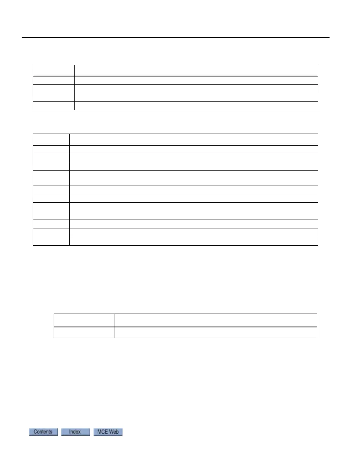
Table 5.12 HC-MPU Board Test Points
Test Points Description
GND 0V
+3.3V +3.3 Vdc measured between this test point and TP GND.
+5V +5 Vdc measured between this test point and TP GND.
+25V Unregulated 25Vdc (+/- 2V) from the HC-CHP board
Table 5.13 HC-MPU Board Terminals
Connector Description
J1 Used to program CPU A. IDC connector.
J2 Keyboard Port. Six-pin DIN connector.
J3 RS-232 Port A. Nine-pin D-sub connector.
J4 External CAN Port. Three-pin Weidmuller connector (CAN H, CAN L, SHLD). Signal for CAN con-
nections outside the controller cabinet.
J5 Internal CAN Port. RJ12 connector/cable to the HC-CHP CAN Hub / Power Supply board.
J6 CPU B Debug Port. Nine-pin D-sub connector.
J7 RS-232 Port B. Nine-pin D-sub connector.
J8 Used to program CPU B. Fourteen-pin header connector.
J9 Low voltage AC input (16V). Two-pin IDC connector.
J10 Optional Ethernet Port B. RJ45 connector.
M1 Ethernet Port A. Serial to ethernet conversion device.
Table 5.14 HC-MPU Battery
Type Original Specification
Sanyo CR2032, 3V, Mn D2-Li cell