Troubleshooting
5-52 Manual # 42-02-2P24
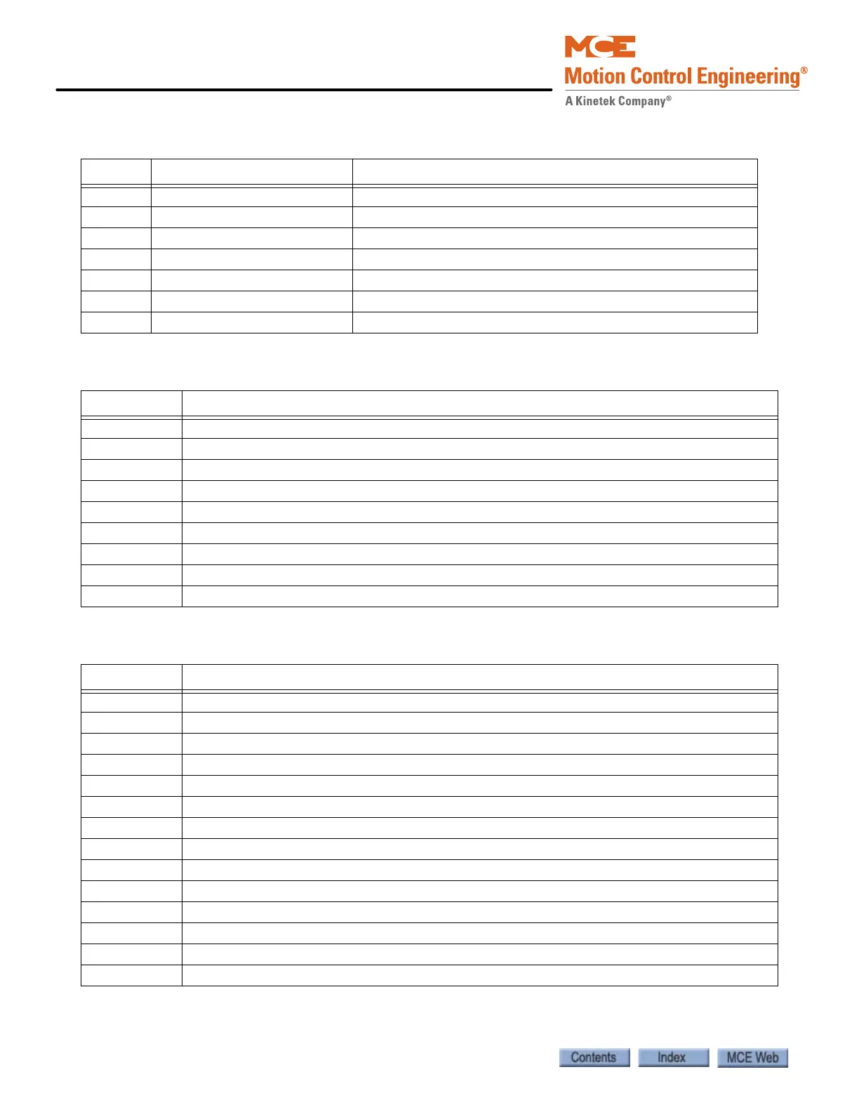
Table 5.9 HC-MPU Board Jumpers
Jumper Setting Description
JP1 A LCD voltage select. A = 5V, B = 3.3V
JP2 - CPU A reset. No jumper provided, only required for testing
JP3 Configuration dependent External CAN network termination
JP4 Configuration dependent Internal CAN network termination
JP5 A Ethernet Port B (optional)
JP6 Open JTAG Debug Jumper. Closed = debug mode.
JP7 - CPU B reset. No jumper provided, only required for testing.
Table 5.10 HC-MPU Board Switches
Switches Description
S1 RSTA: Reset CPU A
S2 RSTB: Reset CPU B
S3 “-” minus push button - decrement setting
S4 “S” push button - select
S5 “+” plus push button - increment setting
S6 “N” push button - next
SW1 Port Selection: RS232 Port A / Ethernet Port A
SW2 DIP Function switches F5 through F8
SW3 DIP Function switches F1 though F4
Table 5.11 HC-MPU Board Indicators
Indicators Description
CPU A ON CPU A is executing its program
CPU B ON CPU B is executing its program
LED2 Reserved
LED1 Reserved
FAULT A fault has been detected.
CPU ON All processors are fully functional.
MLT Motor/Valve Limit Timer: The motor/valve limit timer has elapsed.
TOS Timed Out of Service: The TOS timer has elapsed and the car is out of service.
FIRE Fire Service: The car is on fire service operation.
INSP Inspection: The car is on inspection operation.
IND Independent Service: The car is on independent service.
HS High Speed: The car is running at high speed.
DLK Doors Locked: The door lock contacts are made.
SAF ON Safety On: The safety circuit is made.
 Loading...