MCE Wiring Prints
2-5
2
Motion 4000
MCE Wiring Prints
Become familiar with the wiring prints provided with your control system.
Drawing Number Format
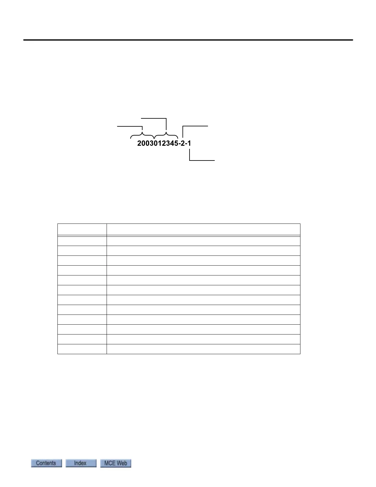
Each print has a drawing number. The drawing number is comprised of the job number, car
number, and page number (see example).
Nomenclature
The following table lists board name and part numbers. Your installation may not use all boards
listed.
Power Nomenclature
MCE job prints and power terminals within the controller are numbered to identify different
power buses:
• 1: The number 1 (one) bus is system Common.
• 2: The number 2 (two) bus is AC power.
Table 2.1 Component Nomenclature
Board Name Description
HC-DB-MOD Front G. A. L. MOD Door Interface Board
HC-DB-MOD-R Rear G. A. L. MOD Door Interface Board
HC-CTL Controller Board
HC-RDR Rear Door Board
TC-MPI Motion Processor Interface to drive
HC-UIO Universal I/O Board
HC-CHP CAN Hub and Power Board
HC-MPU Main Processor Board
ICE-COP-2 Control panel interface board
MC-CPI Control panel interface board
MC-LSI Landing System Interface Board
SC-3HN Three Input Hall Call Node Board
Car Number
Page Number
Job Number
Year