F1: Program Mode
4-33
4
Motion 4000
R2L Redundancy 2L bus. Used to monitor the normally closed contact of an additional 2L relay.
RBAB Redundancy monitoring input for the BAB relay contact. (See description of BAB input).
RDLSR Rear Door Lock Relay Redundancy input (CSA Redundancy) - Monitors the state of the DLSR
relays (there are 2). Activated if either relay is “picked” (a normally open contact from one
relay is wired in parallel with a normally open contact from the other relay to feed this
input). Logic compares the state of the RDLSR input with the state of the DLSR input (the
DLSR input monitors the string of actual door lock contacts) to see if one of the two DLSR
relays has failed in the “picked” mode (if DLSR=0 and RDLSR=1, a failure is declared).
REO Re-Open Input - Houston fire code requires that doors close after completing a Fire Phase I
return. A key switch in the hallway connected to this input is used by the fire person to
reopen the doors.
REOA Re-Open Input Alternate - Houston fire code requires that doors close after completing a
Fire Phase I return. A key switch in the hallway connected to this input is used by the fire
person to reopen the doors at the Alternate recall floor.
REVD Reverse Direction input from the MCE TAPS Traction Auxiliary Power Supply unit. (From
TAPS Rev output)
RGS Redundancy Gate Switch (front) - Monitors the state of the GS relays (there are 2). Acti-
vated if either relay is “picked” (a normally open contact from one relay is wired in parallel
with a normally open contact from the other relay to feed this input). The logic compares
the state of the RGS input with the state of the GS input (the GS input monitors the actual
car gate contact) to check if one of the two GS relays has failed in the “picked” mode (if
GS=0 and RGS=1, a failure is declared).
RGSR Redundancy Gate Switch (rear) - Monitors the state of the GSR relays (there are 2). Acti-
vated if either relay is “picked” (a normally open contact from one relay is wired in parallel
with a normally open contact from the other relay to feed this input). The logic compares
the state of the RGSR input with the state of the GSR input (the GSR input monitors the
actual rear car gate contact) to check if one of the two GSR relays has failed in the “picked”
mode (if GSR=0 and RGSR=1, a failure is declared).
RINAX Redundancy monitoring input for the INAX relay contact.
RUN/A/B Active when car is selected to run on emergency power. A and B are used for duplex.
SAB Sabbath Operation Input - Selects Sabbath Operation in which the car will move through
the hoistway, stopping at landings that are programmed in the Extra Features Menu.
SAFC Car safety string input.
SAFH Hoistway safety string input.
SIMP Simplex Input - Activation causes a duplex car to behave as a simplex. The car will respond
to hall calls registered on its own call circuitry, will not accept hall calls assigned to it by
another controller, and will perform its own parking function independently.
STARTIN Start Input - Used for the START position of the three position Fire Phase II switch for Aus-
tralian jobs. Causes the front and rear doors to close. The car will not proceed to answer car
calls during Fire Phase II until the STARTIN input has been activated.
STDX Programmable, auxiliary step down input. May be assigned to SPIN1 - SPIN6 on HC-CTL
board or to an HC-UIO board and used instead of STD input on HC-CTL board.
STUX Programmable, auxiliary step up input. May be assigned to SPIN1 - SPIN6 on HC-CTL board
or to an HC-UIO board and used instead of STU input on HC-CTL board.
STOP When active, the car will immediately stop so long as the input is active or until the input is
bypassed and the car is commanded to move.
SWG Swing Input. When active will disconnect from the group and act as a simplex, responding
to calls from its independent riser. Disable Local Hall Calls, page 4-16, must be set to NO.
UDF Up and Down direction relay fault input.
UFL Up Final Limit Input - This is a latching input that monitors the up final limit. Deactivation
of this input will shut the elevator down and require a manual reset.
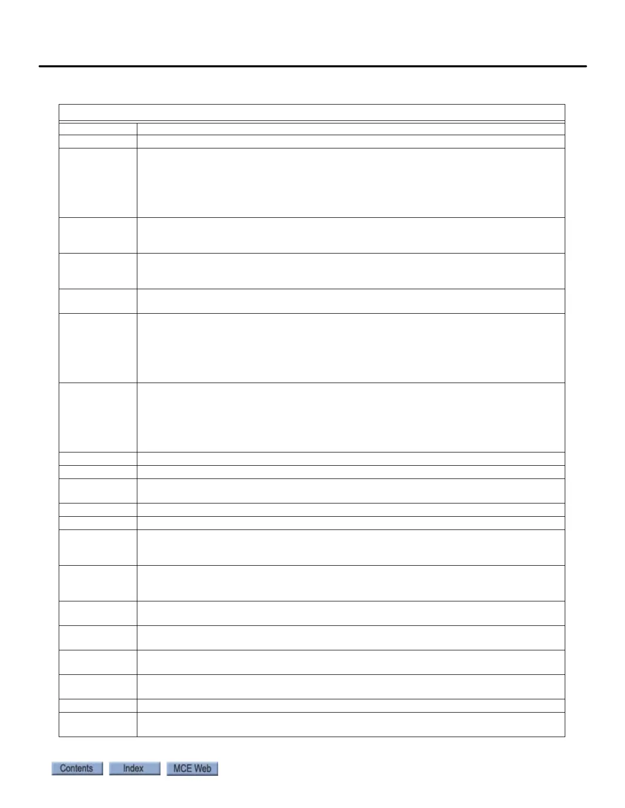
Table 4.6 Spare Inputs Menu Options
Spare Inputs Menu Options