5-18
5-2 Basic Functions
SYSDRIVE MX2 Series USER'S MANUAL (3G3MX2-Axxxx)
5
Functions
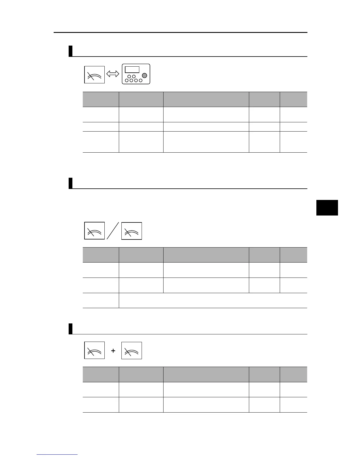
Switching between Analog Current and VR via the FV/FI Terminal
Either Analog Voltage or Analog Current is Used
To minimize the effect of noise, allocate the FV/FI terminal even when either analog voltage or
current is used, and select either current or voltage by turning ON/OFF the terminal. If the FV/
FI terminal cannot be allocated, be sure to short the unused analog input terminal as shown
below.
Specified by a Sum of Analog Voltage and Analog Current
Parameter
No.
Function name Data
Default
setting
Unit
A001
Frequency Reference
Selection 1
01: Control circuit terminal block 02 −
A005 FV/FI Selection 03: Switch between voltage/VR
*1
*1.Volume: Volume on the external Digital Operator 3G3AX-OP01.
00 −
C001 to C007
Multi-function
Input Selection
16: FV/FI (Analog input switch)
ON: Volume
*1
OFF: Current
−−
Parameter
No.
Function name Data
Default
setting
Unit
A001
Frequency Reference
Selection 1
01: Control circuit terminal block 02 −
C001 to C007
Multi-function
Input Selection
−
(FV\FI not allocated)
−−
Wiring
Voltage: FV terminal is used, FI-SC shorted
Current: FI terminal is used, FV-SC shorted
Parameter
No.
Function name Data
Default
setting
Unit
A001
Frequency Reference
Selection 1
01: Control circuit terminal block 02 −
C001 to C007
Multi-function
Input Selection
−
(Need not be allocated)
−−
A
0.0k0
V
A
V
A
 Loading...


