5-25
5-2 Basic Functions
SYSDRIVE MX2 Series USER'S MANUAL (3G3MX2-Axxxx)
5
Functions
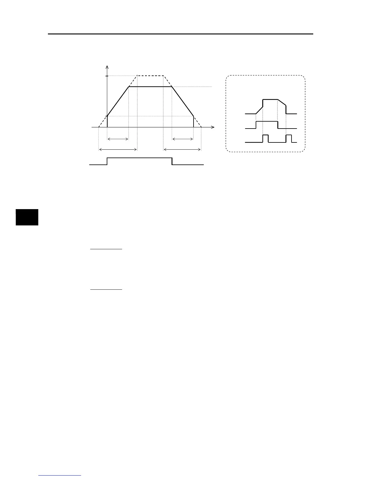
Take note that, as shown in the figure, the actual acceleration/deceleration time becomes
shorter than the set acceleration/deceleration time depending on the set values of maximum
frequency, output frequency and starting frequency.
No matter how shot the acceleration/deceleration time is set, the actual acceleration/
deceleration time cannot be shorter than the minimum acceleration/deceleration time
determined by the mechanical inertia J and the motor torque. If you set a time shorter than the
minimum acceleration/deceleration time, an overcurrent (OC) or overvoltage (OV) trip may
occur.
The calculations of the minimum acceleration/deceleration time are as follows. Use as a
reference.
Output frequency
Maximum
Frequency
A004/A204
Starting
Frequency
b082
Output Frequency
Setting (F001)
Real
acceleration time
Real
deceleration time
Time
F002/F202
F003/F203
RUN command
FW input
When the LAC input is turned ON,
the acceleration/deceleration time
becomes 0.01 s.
Output
frequency
FW input
LAC input
T
L
T
S
N
M
J
M
J
L
t
S
9.55
J
L
J
M
N
M
T
S
T
B
T
L
Acceleration time T
S
=
(
+
)
×
×
()
−
Deceleration time TB
T
L
T
B
N
M
J
M
J
L
T
B
9.55
=
(
+
)
×
×
()
+
: Motor-shaft converted load J (kg
• m
2
)
: Motor load J (kg
• m
2
)
: Motor rotation speed (r/min)
: Maximum acceleration torque based on inverter drive (N
• m)
: Maximum deceleration torque based on inverter drive (N
• m)
: Required running torque (N
• m)