5-75
5-6 Operation Functions
SYSDRIVE MX2 Series USER'S MANUAL (3G3MX2-Axxxx)
5
Functions
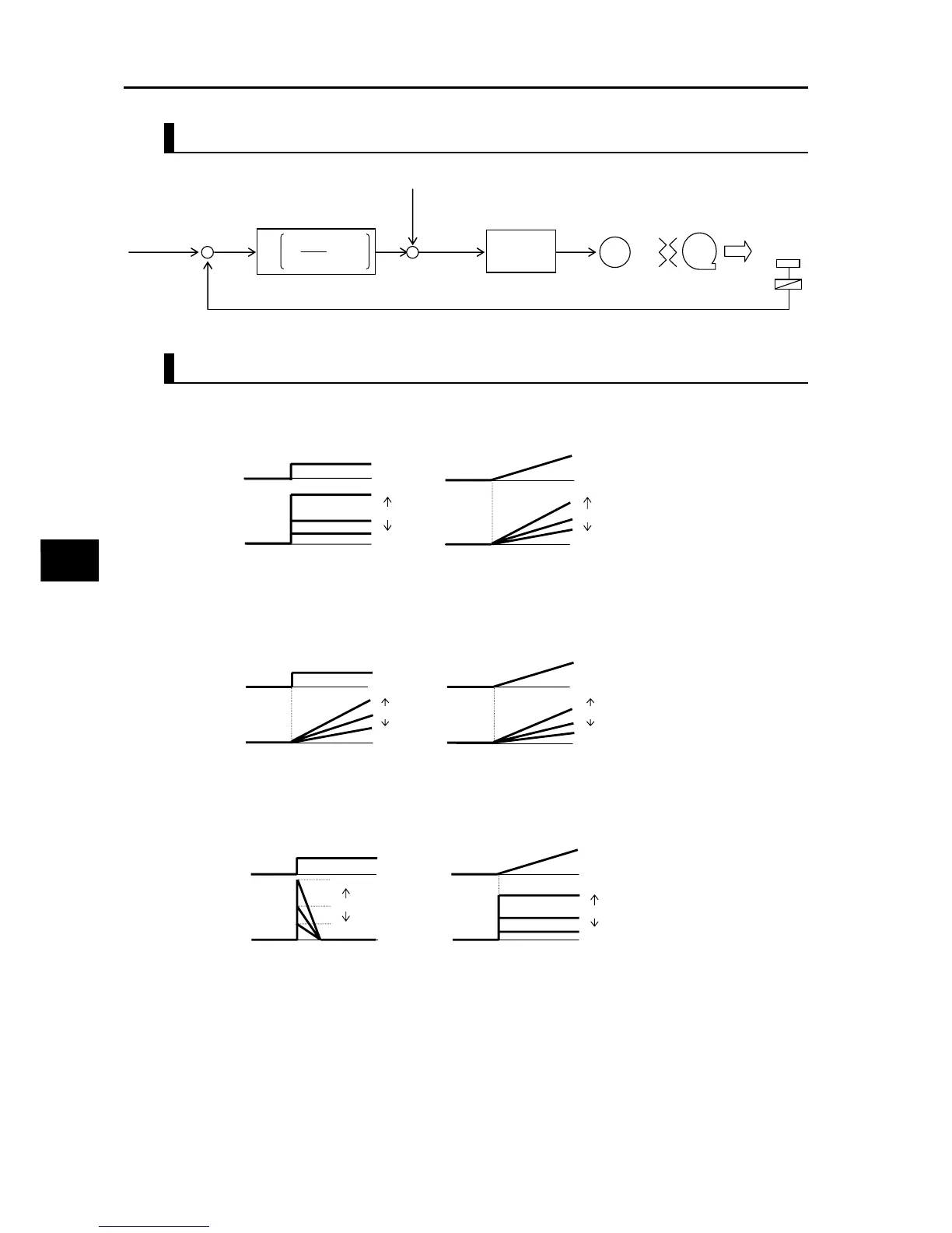
Basic Structure of PID Control
PID Operation
(1) P operation
Operation where the manipulated value is proportional to the deviation (target value
−
current
value).
(2) I operation
Operation where the mainpulated value is proportional to the time-integrated value of
deviations. As the current value becomes closer to the target value, the deviation decreases
and thus the effect of P operation is reduced, and consequently the time needed to achieve
the target value increases. I operation compensates for this condition.
(3) D operation
Operation where the mainpulated value is proportional to the ratio of change in deviation.
Although use of PI operations alone require a response time, D operation has the effect of
compensating for the response.
fs
M
+
−
+
+
Deviation ε
ε: Deviation
sTd
sTi
Kp
1
1
Target value
0 to 10 V
4 to 20 mA
+
·
+
Manipulated
value
Disabled
0 to 10 V
4 to 20 mA
Feedback 0 to 10 V
4 to 20 mA
Normal control
of the Inverter
Transducer
Sensor
Kp: Proportional gain Ti: Integral time Td: Differential time s: Operator
Feedforward
·
=
Target value
Manipulated value
Changes in steps Changes in lamps
Large
Small
A072
Large
Small
A072
Target value
Manipulated value
Large
Small
A073
Small
Small
A073
Target value
Manipulated value
Large
Small
A074
Large
Small
A074