5-89
5-7 Digital Operator/Operation Functions
SYSDRIVE MX2 Series USER'S MANUAL (3G3MX2-Axxxx)
5
Functions
Note: The comma "," in the Display requirements means OR.
User Setting (b037=02)
Displays only the parameters optionally set in U001 to U032.
In addition to U001 to U032, d001, F001, b037, b190 and b191 are displayed.
Data Comparison Display (b037=03)
Displays only the parameters changed from the factory default.
All monitors (d***) and F001, b190 and b191 are always displayed.
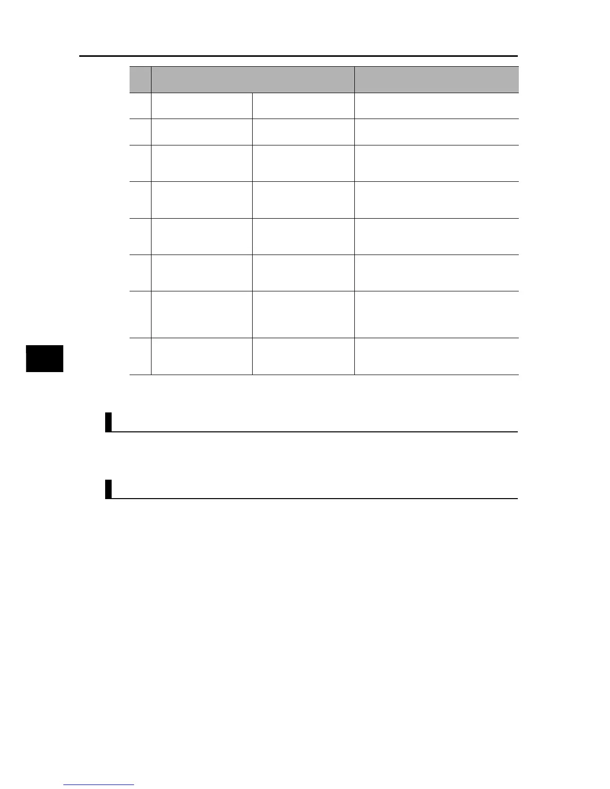
8
Displayed when DC
injection braking is used
A051 = 01, 02 or
C001 to C007 = 07
A052 to A059
9
Displayed when PID is
used
A071 = 01, 02
d004, A072 to A079, A156, A157, C044,
C052, C053
10
Displayed when Co-
inverter communication
is used
C096 = 01, 02 C098 to C100, P140 to P155
11
Displayed during curved
acceleration/
deceleration
A097, A098 = 01 to 04 A131, A132, A150 to A153
12
Displayed when
controlled deceleration
on power loss is used
b050 = 01, 02, 03 b051 to b054
13
Displayed when the
brake control function is
used
b120 = 01 b121 to b127
14
Displayed when the
overvoltage suppression
function during
deceleration is used
b130 = 01, 02 b131 to b134
15
Displayed during simple
position control is used
P003 = 01
d008, P004, P011, P012, P015, P026,
P027, P060 to P073, P075, P077, H050,
H051
No. Display requirements
Parameters displayed when the
applicable conditions are met