2-12
2-2 Wiring
SYSDRIVE MX2 Series USER'S MANUAL (3G3MX2-Axxxx)
2
Design
External Braking Resistor Connection Terminal (P/+2, RB)/Regenerative Braking Unit Connection Terminal (P/+2, N/
−
)
All models in the 3G3MX2 Series have a built-in regenerative braking circuit.
To improve braking capacity, mount the optional braking resistor to this terminal.
Do not mount a resistor whose resistance is lower than the specified value.Doing so may
damage the regenerative braking circuit.
The cable length should be 5 m or shorter. Twist the two wires.
Do not connect any device other than the optional Regenerative Braking Unit or Braking
Resistor to this terminal.
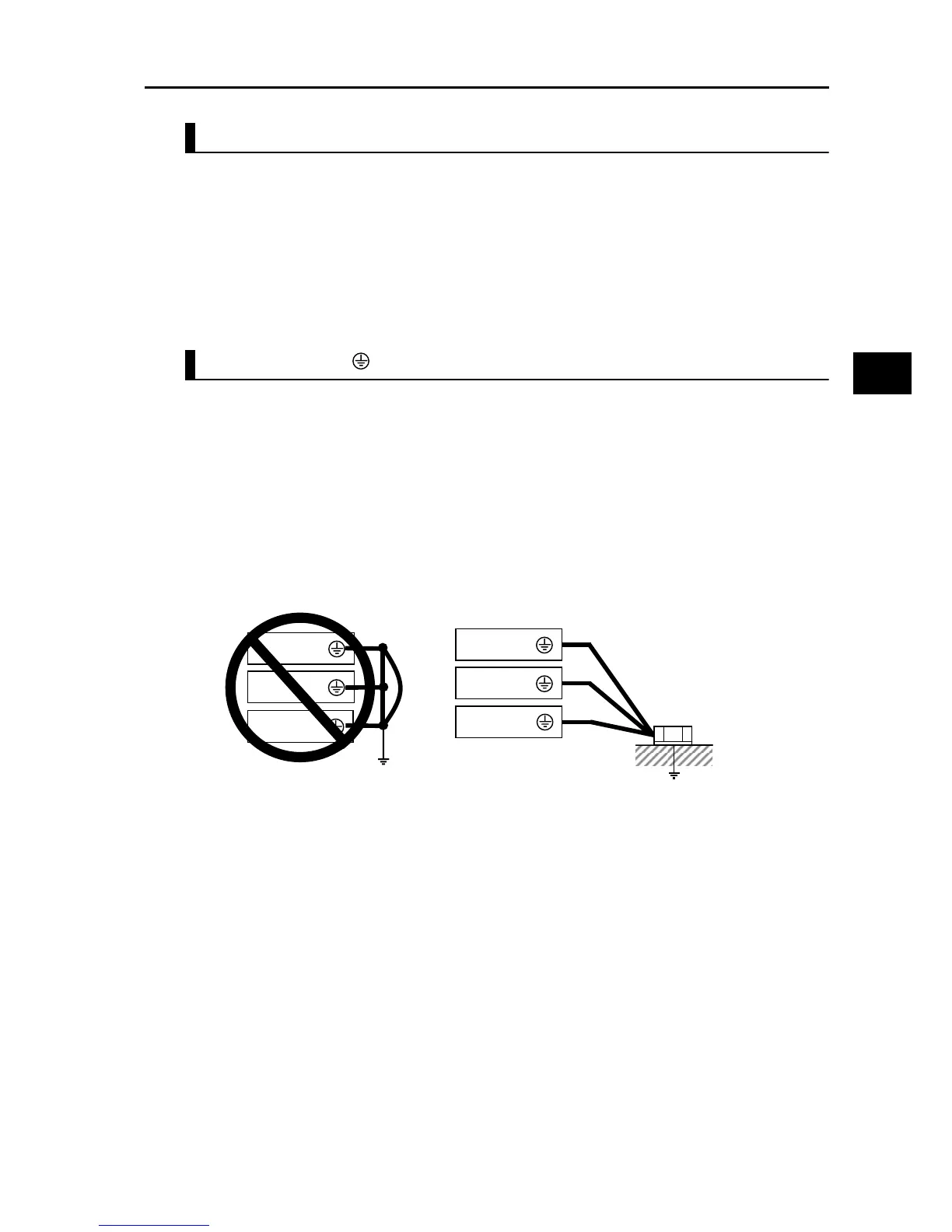
Ground Terminal
To prevent electric shock, be sure to ground the Inverter and the motor.
The 200 V class should be connected to the ground terminal under Class D grounding
conditions (conventional Class 3 grounding conditions: 100 Ω or less ground resistance), The
400 V class should be connected to the ground terminal under Class C grounding conditions
(conventional special Class 3 grounding conditions: 10 Ω or less ground resistance).
For the ground cable, use the compatible cable or a cable with a larger diameter. Make the
cable length as short as possible.
When several Inverters are connected, the ground cable must not be connected across several
Inverters, and must not be looped. Otherwise, the Inverter and surrounding control machines
may malfunction.
Inverter
Inverter
Inverter
Inverter
Inverter
Inverter
Your ground bolt