8-7
8-1 Inspection and Maintenance
SYSDRIVE MX2 Series USER'S MANUAL (3G3MX2-Axxxx)
8
Inspection and Maintenance
Before checking, measure the voltage between P/+2 and N/− at DC voltage range in advance, and
confirm that the smoothing capacitor is sufficiently discharged.
A nearly infinite value is shown in a no-conduction state. (The value shows the range from a few
to a few dozen Ω in a conduction state.)
However, the value may not be infinite if the momentous conduction occurs through the influence
of the smoothing capacitor.
The Inverter or converter is in good shape if the values from various parameters are nearly equal,
though they are not consistent depending on the types of elements or testers.
Tester
polarity
Measurement
value
+
(red)
−
(black)
Converter unit
D1
R/L1 +1
No conduction
+1 R/L1
Conduction
D2
S/L2 +1
No conduction
+1 S/L2
Conduction
D3
T/L3 +1
No conduction
+1 T/L3
Conduction
D4
R/L1 N/
−
Conduction
N/
−
R/L1
No conduction
D5
S/L2 N/
−
Conduction
N/
−
S/L2
No conduction
D6
T/L3 N/
−
Conduction
N/
−
T/L3
No conduction
Inverter unit
TR1
U/T1
P/+2
No conduction
P/+2
U/T1
Conduction
TR2
V/T2 P/+2
No conduction
P/+2 V/T2
Conduction
TR3
W/T3
P/+2
No conduction
P/+2
W/T3
Conduction
TR4
U/T1
N/
−
Conduction
N/
−
U/T1
No conduction
TR5
V/T2 N/
−
Conduction
N/
−
V/T2
No conduction
TR6
W/T3
N/
−
Conduction
N/
−
W/T3
No conduction
Regenerative braking unit
TR7
RB P/+2
No conduction
P/+2 RB
Conduction
RB N/
−
No conduction
N/
−
RB
No conduction
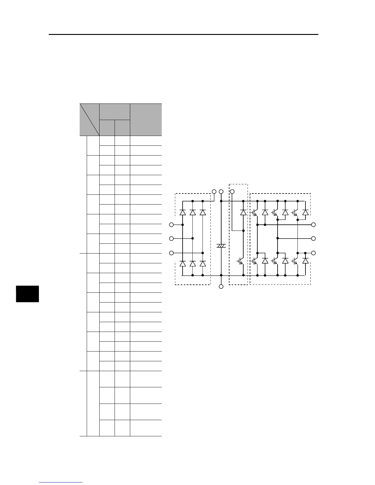
Converter unit
+1
D1
D4
D2
D5
D3
D6
R/L1
S/L2
T/L3
C
P/+2
N/−
TR7
RB
U/T1
V/T2
W/T3
Regenerative braking unit
Inverter unit
TR1 TR2 TR3
TR4 TR5 TR6
 Loading...


