8-9
8-1 Inspection and Maintenance
SYSDRIVE MX2 Series USER'S MANUAL (3G3MX2-Axxxx)
8
Inspection and Maintenance
Note 1. For output voltage, use a measurement device that displays effective values of fundamental wave.
For current and electric power, use a measurement device that displays all effective values.
Note 2. The Inverter output waveform, under PWM control, may have a margin of error, especially at a low
frequency. Testers (general-purpose type) are not applicable in many cases because of noise.
Output power
factor
Pf
OUT
Calculated from the measured values of output voltage EOUT,
output current IOUT, and output electric power WOUT
−
Measurement
item
Measurement point Measurement device Note
Measurement value
reference
PfOUT
=
W
OUT
3 · EOUT · IOUT
× 100 (%)
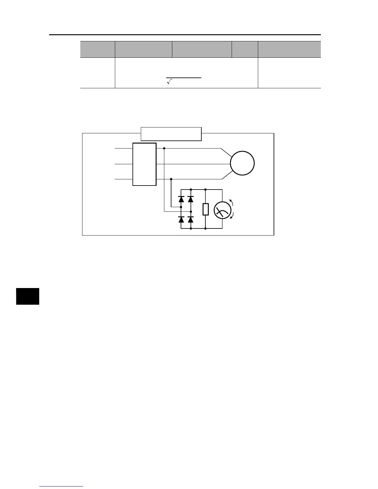
Measurement method
of output voltage
Diode
600 V, 0.1 A max.
(200V class) 1,000 V, 01.
A max. (400V class)
R
T
S
U
V
W
Motor
Moving-coil type
300 V (200V class)
600 V (400V class)
Effective value of fundamental wave
+
−
2 W 220 kΩ
Inverter
VAC
VAC = 1.1 × VDC
VDC