3-8
3-2 Operation Method
SYSDRIVE MX2 Series USER'S MANUAL (3G3MX2-Axxxx)
3
Operation
Command/Reference Input From the Control Circuit Terminal Block
Operates the Inverter by connecting the external signals (frequency setting volume, switch,
etc.) to the control circuit terminal block.
<Setting the Forward/Reverse Direction Using the FW/RV Input Terminal and Setting
the Frequency Using the Frequency Volume>
Setting
Change the following parameters, if necessary:
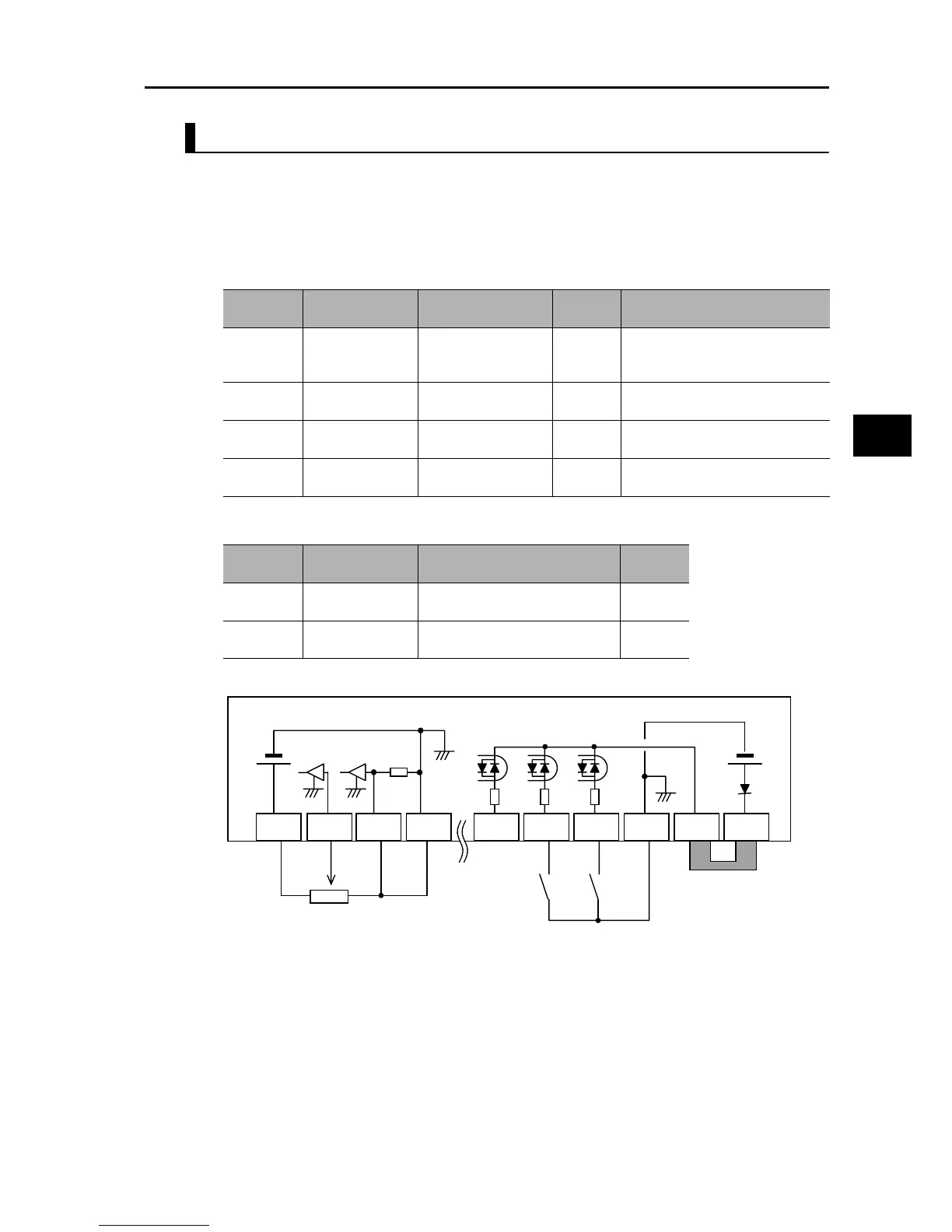
Wiring the Control Circuit Terminal Block
*1 Allocate 16: FV/FI (Analog input switch) to a multi-function input to use as the voltage setting. If terminal
FV/FI is not allocated, the frequency reference becomes the sum of voltage input (FV) and current input
(FI). To use only one of voltage or current, therefore, short the other analog input to the SC terminal.
*2 This wiring diagram shows an example of using the built-in power supply of the Inverter. If an external
power supply is used, refer to "Connection to Programmable Controller (PLC)" on page 2-22.
Operation
Refer to "Test Run" on page 3-10.
Parameter
No.
Function name Data
Default
value
Note
A001
Frequency
Reference
Selection 1
01 (Control circuit
terminal block)
02
A002
RUN Command
Selection 1
01 (Control circuit
terminal block)
02
C001
Multi-function
Input 1 Selection
00 (FW: Forward)
00(FW)
If other input terminal is used, the
parameter number becomes different.
C002
Multi-function
Input 2 Selection
01 (RV: Reverse)
01(RV)
If other input terminal is used, the
parameter number becomes different.
Parameter
No.
Function name Data
Default
value
F002
Acceleration
Time Setting 1
0.01 to 99.99 s 100.0 to 999.9 s
1,000. to 3,600. s
10.00 s
F003
Deceleration
Time Setting 1
0.01 to 99.99 s 100.0 to 999.9 s
1,000. to 3,600. s
10.00 s
10 VDC
F/R
setting
STP
setting
STA
setting
Frequency setting
volume
*1
*2
FS
FV
FI SC S3/GS1 S2 S1 SC PSC P24
24 VDC
Reverse
input
Forward
input