About Controls and Connectors
Related Information
■
“Back Panel Components and Cable Connections” on page 18
■
“About System Components” on page 19
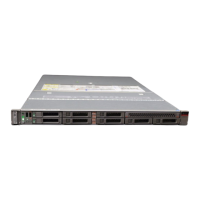
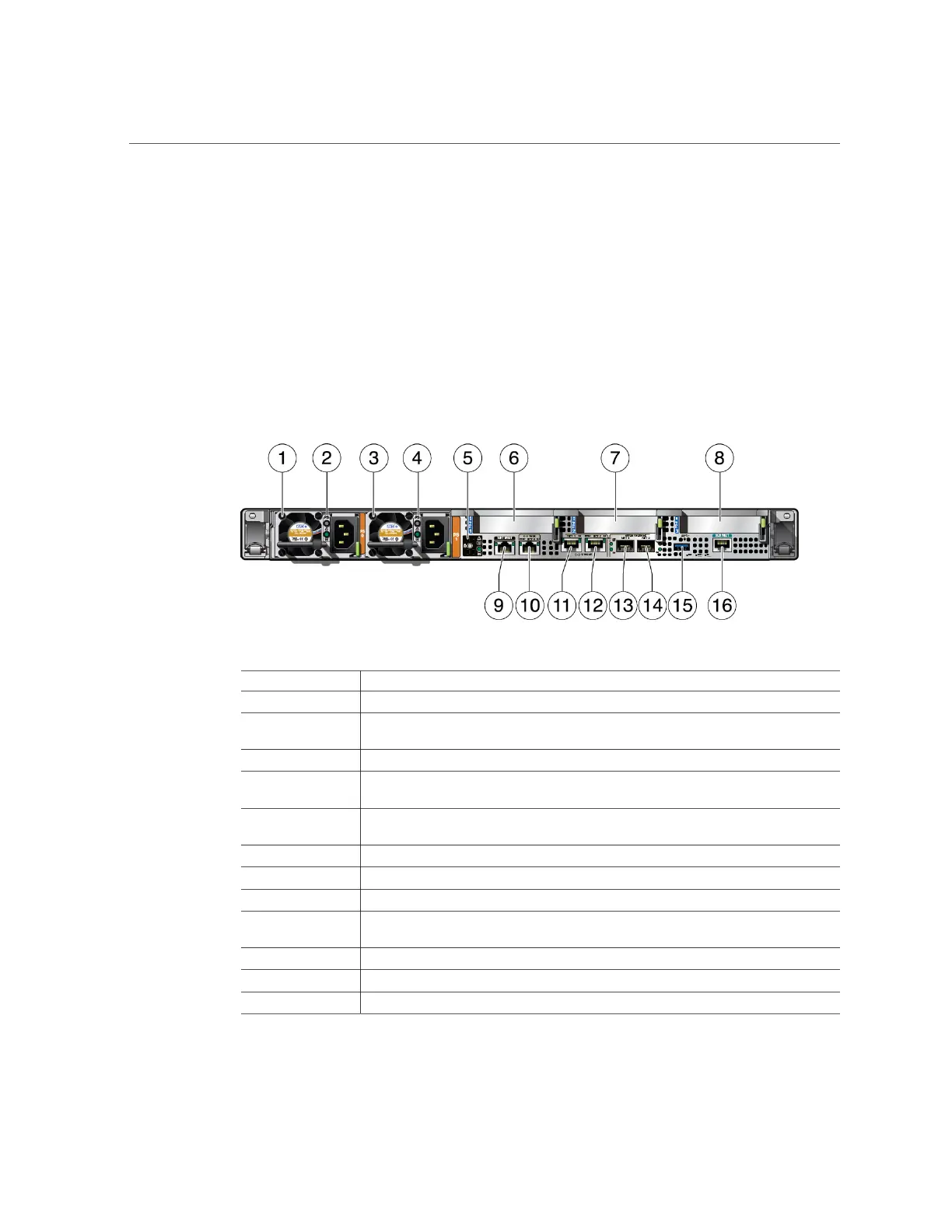
Back Panel Components and Cable Connections
The following figure shows the Oracle Server X7-2 back panel and the location of power
supplies, status indicators (LEDs), connectors, and PCIe slots.
Call Out Description
1 Power Supply (PS) 0
2 Power Supply (PS) 0 status indicators: Fault-Service Required LED: amber; AC OK LED:
green
3 Power Supply (PS) 1
4 Power Supply (PS) 1 status indicators: Fault-Service Required LED: amber; AC OK LED:
green
5 System status indicators: Locate Button/LED: white; Fault-Service Required LED: amber;
System OK LED: green
6 PCIe card slot 1 (Nonfunctional in single-processor systems)
7 PCIe card slot 2
8 PCIe card slots 3 and 4
9 Oracle Integrated Lights Out Manager (ILOM) service processor (SP) network management
(NET MGT) RJ-45 10/100/1000BASE-T port
10 Network (NET) 10/100/1000BASE-T RJ-45 Gigabit Ethernet (GbE) port: NET 0
11 Network (NET) 10GBASE-T RJ-45 GbE port: NET 1
12 Network (NET) 10GBASE-T RJ-45 GbE port: NET 2
18 Oracle Server X7-2 Service Manual • October 2017