Install the NVMe Cable Assembly
Note -NVMe cable assembly, part number 7115195 is required to connect the motherboard
NVMe connectors to the disk backplane.
Note - Each NVMe cable contains a matching label that corresponds to connectors on the
motherboard and the disk backplane. For example, the NVMe cable labeled A, plugs into
motherboard NVMe A connector and the disk backplane NVMe A connector.
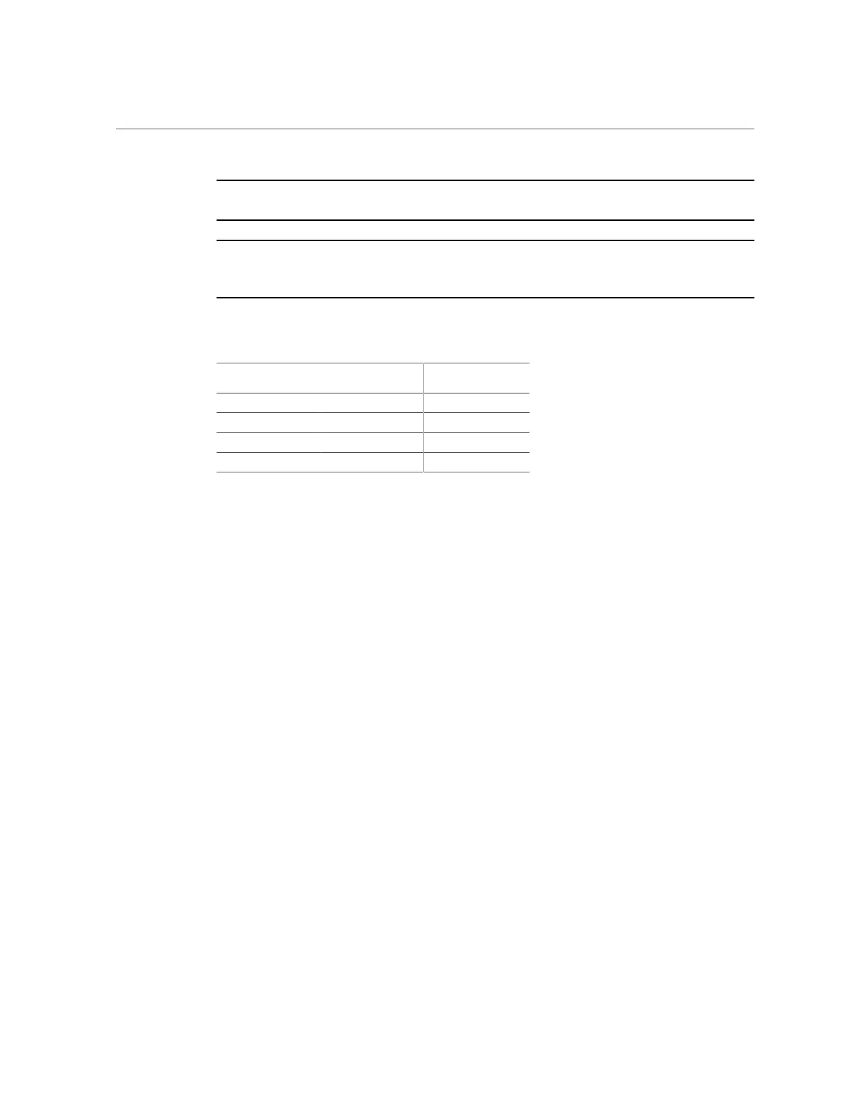
Use the following table to ensure proper NVMe cable connections.
Motherboard NVMe
Connector
Disk Backplane
Connector
Storage Drives
A NVMe A 0, 4
B NVMe B 1, 5
C NVMe C 2, 6
D NVMe D 3, 7
3.
Connect the NVMe cables to the disk backplane [2].
To ensure proper connections, see the NVMe cable connections table in Step 2.
4.
Install the mid-wall into the server chassis [3, 4].
a.
Lower the mid-wall into the chassis.
Ensure that the green captive screws are aligned with the screw holes on the bottom of the
chassis.
b.
Using a Torx 10 screwdriver, tighten the four green captive screws to secure
the mid-wall to the server chassis.
5.
Install all of the server fan modules.
See “Install a Fan Module” on page 84.
6.
Return the server to operation.
a.
Install the server top cover.
See “Install the Server Top Cover” on page 210.
b.
Return the server to the normal rack position.
See “Return the Server to the Normal Rack Position” on page 212.
190 Oracle Server X7-2 Service Manual • October 2017