290 Adding Optional Hardware
33 Mount the IEM1 circuit card onto the access door filter bracket and snap it over the four pegs on the
bracket.
34 Use a 2.5mm hex wrench to install the M4x10 screw to secure the IEM1 card in place.
35 Insert the I/E cable into the slit of the protective cable sheath. Bend the cable sheath away from the I/E
cable and gently press the cable into the sheath.
36 Drape the I/E cable (W6) over the top damper and insert the cable’s connector into the top connection
on the IEM1 card until it snaps into place.
37 Use a 2.5 mm hex wrench to secure the I/E cable to the door using a P clamp.
Place the P clamp around the cable (not the sheath) and secure it to the upper damper bracket
mounting hole.
38 Place the second P clamp around the I/E cable and secure it to the carrier bracket in the roof of the
expansion module using a 2.5 mm hex wrench to install one screw to the right of the vacant cable carrier
screw holes.
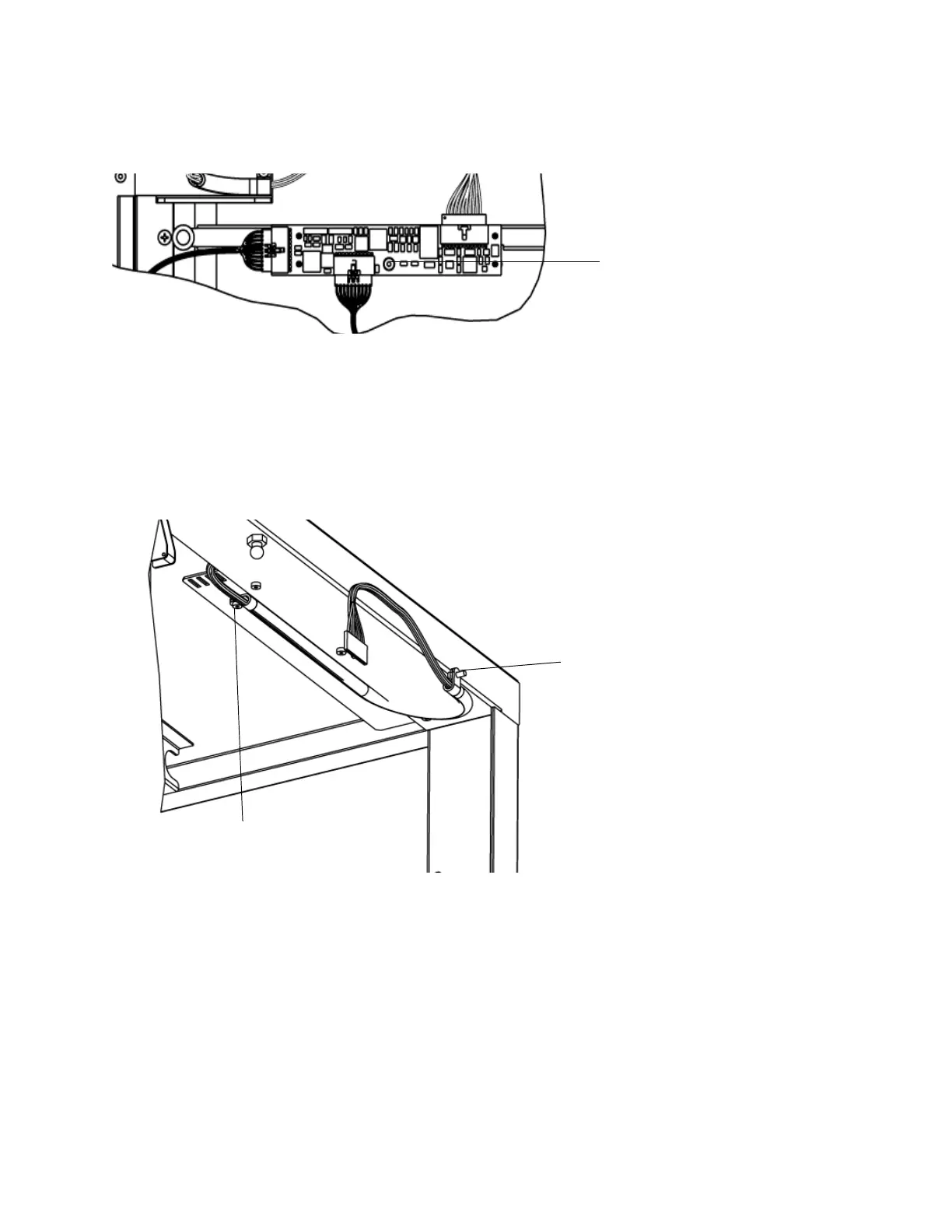
39 With the access door fully open, verify that the I/E cable has a small amount of slack.
When the access door is closed the slack from the I/E cable forms a "U" shape and protrudes toward
the firewall. See the following illustration.
40 Close the access door.
41 From an adjacent module, view the I/E cable and verify that the I/E cable is within 12.7mm (1/2 inch)
from the frame cable bracket’s main surface and that the cable is flush within +/- 12.7mm from the edge
of the frame cable bracket. See the following illustration.

 Loading...


